You can redefine your coordinate system and view planes at any time, so I don’t know that it matters a whole lot.
Horizontal / vertical are sketch shortcuts when sketching, you could use parallel and perpendicular instead, it’s just not as convenient.
Are aware that you can change the orientation of the sketch axes so that horizontal/vertical are aligned with whatever you want?
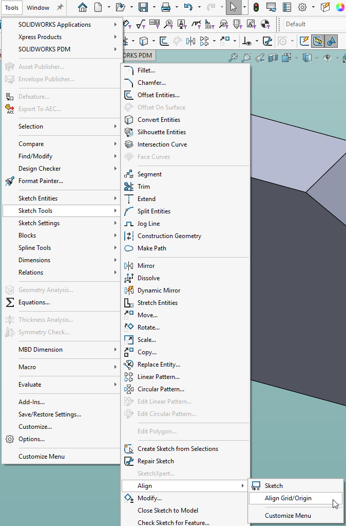
Here’s a sketch on the front face of this part where I’ve placed the sketch origin at one corner and aligned the y axis with the sloped face:
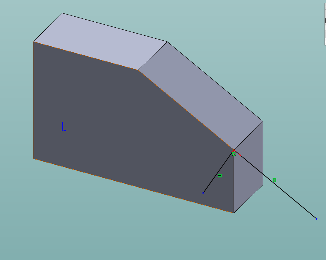
As you can see, what is horizontal and vertical are completely under your control.
And we don’t work with 100% rectangular parts. So horizontal and vertical will lost it’s meaning.
Project from another sketch. Parallel and perpendicular. No vert or hori.
Free your mind from earthy constrains.
Always frustrating when I convert from a SolidWorks authored model into Solid Edge. Luckily it is easy to rotate the model and “fix” it.
as a machinist, model maker, prototyper… who cares? Not me because depending on how the part was built, Y, Z up or top down in an assembly where the XYZ zero is off in space I have to make my own coordinate in CAM of the part.
Now when I taught SW to students I preached part oriantation for how you want the drawing to be for the front view, aka most detail that defines the shape should be front.
again each their own.
I have no experience in a big company, but it surprises me that people can be trained to generate CNC code, but aren’t capable of orienting the part in the context of the machine.
Does design have to create a CS for every setup?
Does design have to create a CS for every setup?
no! thats for the machinist to do as they are the ones setting up how they want to machine it
Edit: After re-reading the first part of your reply, are you saying the machinist has no idea?
most machinist can design a part better for machine orinentation that an engineer…
I model with “Rotate About Scene Floor” always on. Other engineers here hate it, but I like always having that orientation reminder. For parts that do have a consistent orientation in an instrument, I like having them oriented correctly. I think it makes it easier to think about the changes I am making.
Dwight
In 25 years of SolidWorks, I’ve never heard a complaint or request to change the coordinate system or orientation of a model. The closest one time was when I had to export a large layout assembly of our product into Revit for a customer and there was a global “building” origin csys. I just added a SolidWorks csys at the location and exported to STEP while selecting that csys instead of the default. Our model went into Revit in the correct location and oritentation.
sometimes i do export things a on a certain origin because there is a very specific way i want it to get machined. If it isn’t oriented that way in cam software, the machinist goes off script and blows away critical geometry.
Dave,
Hey, I see your from Cheeder.
I’m originally from Cedarburg, went to NWTC in Green Bay for Model Making back in 1983-85 and now run the Student machine shop here at Arizona State University for the school of Engineering for the last 18 years.
My brother worked for Strowig in Richfield for 30 as a Tool and Die machinist, now retired.
nice to meet ya derh hey.
lenny
@len_1962 an old coworker of my went to nwtc for model making as well! Strohwig was on my short list when I was forced to look for a new job, but I landed at Triangle Tool - shorter commute. Next time im out in AZ i’ll look you up ![]()
next time I back I try to look you up as well…
Worked in a large corporation that tried to make inventor Z up. Inventor is Y up by default which was fine for modelling but an absolute pain for drafting 2d as we had to create reference view to re-orientate the parts in the 2d drawing it was a nightmare, for isometric views and exploded view as you had to create the reference view twice and inventor had a separate file to do exploded views.
We eventually pointed out the hour lost reorientating parts in 2d was higher that getting the Cam operator to reorientate the parts in the Cam software. And switched back to Y up.
I would use the software default orientation. if you want Z up use NX SE or Catia or Creo. these are Z up as they have cam packages available for them since they where first concived.
CAM don’t care which way the part is modeled.
We got vertical and horizontal mill. The part might rotate a few times during machining.
Which way is up for the lathe?
My “Z-up” in Inventor:
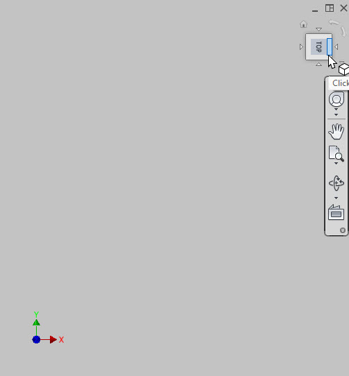
What changed is the view cube. Set it to whatever you want.
Oh, also. Need to update all Templates. Only new files will be Z-Up.
What is the definition of “Z-Up”?
Beside Z point up.
Which one is “Front”? Y? X?
TL,DR; -y would be “front”
When it comes to “standards” I tend to feel that we have more than enough.
https://imgs.xkcd.com/comics/standards.png
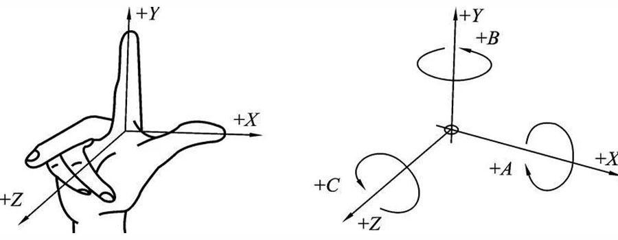
So instead of thinking up something on my own I like to see if there may be some majority. The “Right Hand Rule” goes back a long time and is applicable in many sciences. If one says z axis is vertical up, then y must be 90 degrees counter clockwise to x. Since nearly every thing I’ve seen with an x axis (except marketing stuff) shows x positive going left to right, I’d say y positive must be going back.
After I shared my template on Linkedin, it’ll be standard in a few years.
Funny, when I hold up my fingers like that, I find +Z up and +Y pointing away from me
However, I do find myself a staunch proponent of +Y up in SolidWorks ![]()