In my company we are a small team that we are starting our mechanical engineering operations and are in the lucky position to define many of the initial “standard” practices when it comes to CAD.
We are trying to standardize on a default orientation for modelling our parts. Some of us use the Z-up configuration and some use the Y-up configuration.
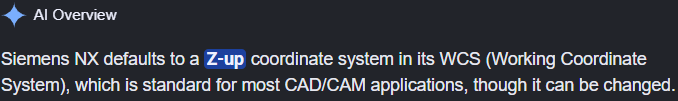
I know that historically, Y-up has been the default orientation for most CAD software (including SW), leading to the issue of parts needing to be reoriented when used in other applications where traditionally Z axis is used for part height (e.g. CAM).
When using Z-up configuration in SW, the orientation of the part when sketching behaves weird… the sketching planes seems to always orient in a different way that you naturally expect it to (has anyone noticed this?). Having said that, you do end up with the Z-axis pointing up as you would expect (i.e. a more “natural” or “consistent” orientation when assembling and processing parts). Y-up modelling is preferred by some mostly as it is what they are used to and the part orients as expected when creating sketches.
I was wondering if there are any obvious advantages of one over the other, or any particular reason why one should be favored over the other? Does any one has any strong views about this? Your thoughts and comments will be appreciated.
I would have loved to never be exposed to a Y-up CAD software!
But SolidWorks is built like that. I don’t know if they made some changes in the last version but up until SW2025 it doesn’t work properly. They added the option to use Z-Up but the standard planes are not updated properly, the relations between them are not working, as you noticed.
The solution is not a custom template and some new saved views, as my VAR keeps telling me, is some assumptions deep in the code that must be changed.
Most of the equipment I design has no concept of up. It doesn’t sit on the floor or hang on a wall. It often runs on a track attached to a pipe that might be horizontal, vertical, at an angle, etc. So X Y and Z area meaningless, as are Front, Top,Right, etc. I changed our templates and renamed the planes Plane1, Plane2 and Plane3.
As for sketches orienting differently than I expect, they never do, because I don’t place expectations on that. I turn off ‘Auto-rotate view normal to sketch plane on sketch creation’ in the System options and therefore I’m never ‘surprised’. The sketch origin tells me which way is ‘horizontal’ (small arrow) and which way is ‘vertical’ (long arrow) and that’s all I need.
Now, if I were designing fixed position equipment and mating everything based on common origins and such, that would be a different matter. But even then I would simply pick the SW default, because the choice doesn’t matter, as long as everyone does it the same way.
I assume SW behaves well in the Y up configuration. It is terrible at Z up. (Z down?)
I’ve used several CAD packages, and SW is the only one that didn’t recognize that a large portion of their customers live in a Z up world. Maybe the others started as Y up, but they could be configured to operate properly as Z up.
I think your assumptions about the origins of the differences is incorrect. AFAIK, the aircraft and automotive industries, at least in the US, have always been Z up. (edit: I could be wrong. Just because the industry uses Z up, doesn’t mean the CAD software was written for that methodology.)
When I design in CAD, I don’t “look at” sketch flat. I’ve turned off “look at sketch” option for a long time. Just rotate it so I can see what need to see.
Sketches are created inplace from face on the part so the sketch orientation is irrelevant. Don’t really care which way is x or y. They’re projected lines. Parallel, perpendicular, collinear. Not up, down, left, right.
Free your mind. Don’t constrain it to a single coordinate system.
Option 1. Bring sub assembly into master assembly. Mate origins.
Option 2. Bring sub assembly into master assembly. Mate Master front plane to whatever plane is correct in the sub assembly. Flip direction if required. Repeat for other 2 planes.
Yes, it is only a few seconds. Do that a couple of times a day x n employees and the time adds up.
I would work off the standard template that comes with SolidWorks. Then customized it as little as possible to create the templates that you need for your products. It never fails that I can replace one part with a similar part and it was modeled off of the right plane and the one I am replacing was modeled off the front plane. So part is flipped 90 deg, and needs to be remated to fit properly. Set up and document the standards to model and try to make sure that everyone follows the same procedures. It is all kinds of fun to model a part and then later find out that there was a template that could have been used because no one said so or there was no documentation on how to do it or where to start looking for anything. A perfect time to start a wiki page and work on documenting everything you can so others can follow.
When working with Master, every part use the same Master Sketch/SSP. It doesn’t matter which way is “up”. As long as part and Master use same coordinate system.
Hence setup part and assembly template to use the same coordinate system.
If design is split to different “vendor” then they all need to use same system. Again, Z-up, Y-Up, X-Up doesn’t matter. Pick one.
i guess it never bothered me that Y is up until i started playing minecraft with my kids and moving left/right, back/forth was X & Z +/-…
personally, i dont care how i model things in SW. I will make either a machining coord sys in sw to export from or i will make it in cam for how i want the part oriented.
90% of the time it “doesnt matter” which way is which for me in designing plugs/molds. Where it does matter is in the automotive world when they want everything in “car position”. then the direction of things matters a great deal
Everything I’ve seen is Z up except SW and lathes.
Up doesn’t matter; until it does, then it matters a lot.
Don’t try to make SW do Z up, AFAIK as of 2026 the side effects of the work arounds are worse than just living with imports landing on their face and exports loading in other systems tipped over. Either way, most systems can do a move body.
Most importantly, the people who started out with Z up worked with their drafting tables’ incline set below 45 degrees from horizontal; people with Y up had it above 45 degrees.
Lastly, muscle memory has a tremendous effect on efficiency, either helpful or hindrance.
I agree that what is considered “UP” is arbitrary and that in the end you can decide this and/or control it with a master part as @Frederick_Law suggests. However, I also think that not all parts/assembly need a master part and that the orientation of the parts do matter as @SPerman mentions.
I think the biggest problem is the way SW orients sketches. I know you can orient a sketch whichever way you want, and that you don’t necessarily need to have it normal to the screen. But the problem is that the definition of what is “horizontal” and “vertical” changes with the original definition of the sketch! So you could reorient a sketch to the way it is logical for you (or just the way you want it), only to find out that horizontal tools make everything vertical on that orientation, just because the way the sketch has been automatically defined. I also think this is a problem deeper in the code of SW, just as @mgibeault mentions.
I used to work with Pro/E and I loved that you could define the references that you wanted for your sketches, so you could control exactly what you wanted and use the features that you wanted for references… yes, I know, not very “user friendly”, but it really allowed you to control your models the way you wanted.
 \"PINKY UP\" Official MV")