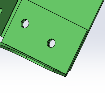
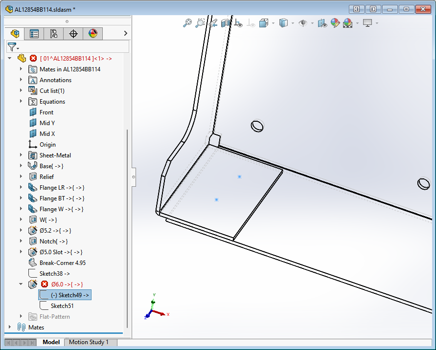
This is a very simple sheet metal part. I have a Ø6.0mm hole added with hole wizard. When I edit hole’s sketch (Sketch49) and add a point (near in blue circle), Solidworks keeps giving me Zero Thickness error and denies to add the hole.
How adding a hole to an existing hole may cause zero thickness geometry?
When I do a forced rebuild on your part after opening it I get an error on Flange W that the part intersects itself. Appears to be related to the two flanges not having any clearance (1.6mm material & 1.6mm offset). If I increase the offset to 1.61 the error goes away and I can create holes through the flanges.
Solidworks Sucks in sheet metal. They know it and that’s why they have an option to bypass the error you mentioned.
0 clearance is different with intersect. We are manufacturing several thousands of these kind of brackets and it’s absolutely possible. If we have a clearance between two flanges, how can we spot weld them?
Moreover, SPerman was able to add the holes without adding a gap between two flanges.
I have had these kind of bends in previous versions and never have seen this. Maybe something have changed in 2022.
Million thanks for taking your time and looking into this.
Can you tell, why I have a hole and nothing’s wrong. And only the second hole throws this error?
Having no gap between two flange isn’t different with zero thickness geometry?
If I have two extrude one over the other and don’t merge them, SW doesn’t give me that error.
I created a section view, so I could look normal to the face, to better understand where I was placing holes.
I can get it to fail under 2 conditions.
1: If the holes breaks through the edge of either the top or bottom flange.
2: If the holes overlap.
Otherwise, I cannot get it to fail. My best guess is that the 2nd hole you are placing breaks an edge, but it is difficult to tell if you are looking on an angle.
Whether or not you get errors probably depends on this setting:
image.png
Solidworks sucks at zero thickness geometry. This is a limitation of the Parasolid kernel that SW is built on. As you mentioned, there’s an option to ignore self-intersection in sheet metal features. And as you’ve discovered, it’s probably a bad idea to use it. You can get your flanages to build, but intentionally creating an invalid body and then continuing to perform operations on it is asking for trouble.
Of course you can physically manufacture them. There’s a lot you can do in CAD that you can’t do in metal and vice versa. However… If were wanting to talk about the differences between CAD and real life, there’s some amount of clearance in there somewhere. In fact, especially after you spot weld, I’m pretty sure every bit of that overlap has clearance except for the actual positions of the welds.
There’s no reason for us to keep checking your files. You’re modeling them using poor practices, failing to account for the limitations of the tool you’re using. There are a lot of things SW will let you do that you probably shouldn’t do if you can at all help it.
Which CAD you used allow 2 features with 0 distance?
SW and IV won’t allow that.
SW will have ZTG error.
IV will combine the face and it won’t flatten.
Best practice is make a small gap, 0.001" or 0.0001".
Ok guys, I’m going to argue that you aren’t actually manufacturing a perfect 0 gap part. There is a gap, it’s small but its there. You can put a 0.001" gap between the flanges and the issue goes away. I know if seems you shouldn’t have to but…well…SolidWorks. Someone mentioned parasolid as the culprit…does Solid Edge have this issue?
I cannot open the attached file, but not sure what the poor practices is all about. From the info in this thread there’s a lapped corner with the flanges being tight together and then add a hole feature through them or am I missing something? I just did that in Solid Edge (parasolid) and I cannot get it to fail. I agree that trying repeatedly to do things that the CAD system doesn’t support is bad practice. But how does one know all the things a CAD system cannot do? I assume by trying and failing or by guidance of others. They sure as heck don’t cover all these pitfalls in the training!