Nothing special for that. I’d guess we had dozens if not hundreds of files in our data set like this. Out of ~40k+ .psm files.
Now, there may have been times where downstream features that interacted with these flanges may have gotten flaky and I’ll agree it could have been due to the no-gap between the flanges. I just cannot think of any scenarios off the top of my head to try out.
Took me a bit to remember how to go in to change the default precision. I think you are correct that there is a gap; maybe 0.0004". I’m checking to see if SE does that automatically or just dumb luck on my part. I just made the flanges and selected the default flange position that would make them tight.
From what I can see Solid Edge takes the liberty to offset the face that the flange comes off of by 0.0004" so that the lapped flange has a gap. The inside radius and flange thickness are still nominal. I was able to put a manual offset in the flange = 0.0004" and Solid Edge then fired off the ZTG error.
There is no way to deal with the ZTG, just guide the user away from it.
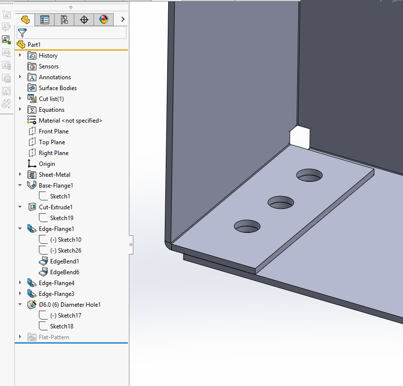
SOLIDWORKS can do this just as well. Something is out of whack in the original model, but recreating it in SW2022 I didn’t have a problem:
image.png
There’s no gap: