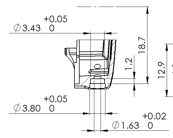
Is it possible to suppress the zero with a, for example, +0.05/-0.00 bilateral tolerance.
I don’t see a way other than just typing “+0.05” into the dimension text box after the (DIM).
I’m pretty sure I’ve never seen it that way on an actual engineering drawing. Is there a drafting standard that allows this?
Leave the zero it explains the dim better for the quality guys to be able to check it.
With out the zero on there would the title block tolerance take effect?
Agreed. Leaving out the 0 would add confusion.
One thing that I believe in:
If the person making the part or assembling the design has to come and ask me any questions at all about it, then I have not put enough information on the drawing.
Happens to me to often the way it is.
Bit of a conversational diversion but other than maybe for shaft fit limits I’ve always found Bilaterial tolerance a bit of an odd choice; why not use Limit tolerance as it takes up less space on the sheet?
Thanks all, was asked to copy an existing Pro-E drawing which had the zeros suppressed.
You are quite right, standards require the zero, for example in my case BS8888 “If one of the two limit deviations is zero, this shall be expressed explicitly by the digit zero shown without sign”.
So the zero stays ![]()
Bilateral tolerance better communicates design intent to checkers or future users of the part etc. I haven’t memorized the table of ISO shaft/hole fit tolerances. When I get a drawing from another engineer for checking, I want to see both the fit class (e.g. H7) and the bilateral tolerance assiciated with it. When I read dimensions of a component in a catalog, I want to be able to recognize quickly which fit class I need to choose for my mating part without digging out tables and doing math.
Yes, that’s why I persist with bilateral on shafts / shaft holes (in conjunction with the class) as that would be a lot of numbers to expect someone to remember if you just gave H7 / g6 etc.
Otherwise I like just using Limit as all the machine shop needs to know is the maximum and minimum sizes they’re allowed to make something. Having 3.43 +0.05/-0.1 means they need to do maths, 3.48/3.33 gives them absolute clarity.
I’m back and forth on this. Limit makess a lot of sense for manufacturing. For engineering I prefer bilateral and unilateral so I can see the nominal dimensions the part was designed around.
The machinist making the part is going to program the nominal dim to the center of the tolerance to make the part, that allows for the most run-out both directions. In practice if a shaft has 1.000 +0.00/-0.010 we would program it to 0.995 and have +/-0.005 in both directions. For anything other than shaft fits, because they are a standard, it makes more sense to just go with bilateral tolerances
I can’t say what they programmed to, but I’ve had a machine shop consistently deliver to the bottom of the tolerance. I assume that they shoot for the low side, knowing they can always make the hole bigger. Once it is in tolerance, the nominal is not a concern.
Probably depends on how it was made. I think CNC folks like to program to the middle, push the button, and trust the machine. Old-fashioned manual like to sneak up on the MMC limit because, as you said, you can always cut off more metal.
Not every part is machined, lots of processes out there that don’t have perfectly symmetrical variance distributions.
.995 ±.005 is NOT the same as 1.000 + .000/-.010; those mean different things.
Assuming that you intended the “+0.010” to say “-0.010”, they certainly do mean the same thing on a drawing. They show the acceptance limits of the produced part. It’s certainly true that many processes create asymmetrical variation distributions, but this has to do with SPC and production, not drawings. There is not a single part that you can accept or reject differently between the two tolerances you’ve mentioned, just based on that. You may have arrangements outside the drawing that specify how capable the process must be, and where within the tolerane band that capability must lie, but as far as the drawing itself those tolerances are the same.
Thanks for the correction, I fixed my typo.
It has been my experience that what you state can cause communication failures. Unfortunately there are lots of variables and these are not black or white. There’s more on the drawing than whether the part is in tolerance, which is hopefully black or white.
On a drawing they absolutely are the same.
I’ll stick with using limit dims to get 1.00/0.99 on my drawings to have it take up way less space and still get the same spec part at the end ![]()
Speaking of communication failures… I want to make sure I understand completely what you are saying.
Can you explain the difference in meaning that you are referring to? If you sent me a drawing with various ways of writing the same tolerance, what would you expect me to understand based on the different ways of writing it?
Yea, I would like to hear how .995 ±.005 is NOT the same as 1.000 + .000/-.010 as well.
On a drawing they say the same thing, if the hole or shaft is .990 to 1.000 in size it is a good part based on either. There is some meaning in a one sided limit that makes most of us assume it goes into the bearing or bushing, but that is conjecture without some note or other assembly info.
In the world today where model information is used for machining, laser cutting, or other manufacturing processes the +/- limits tend to be better since you wouldn’t have to program an offset in CAM packages to get the correct size feature.
Well, I’m not a detailing expert, so I’m likely missing some concepts that are considered common knowledge.
TL, DR; It’s not always just pass/fail; there’s a scale between best, good, acceptable, and unusable. Both in end product performance and cost, and I seldom see them agree, so it’s always a compromise.
Long version:
With this one specifically, I’ve been told plenty that the two tolerance notations are identical. And I get it, they are identical mathematically and whether or not the part meets the contractual document (drawing.) Speaking strictly pass or fail, yes they’re the same. After that, I get lost is in conveying what’s “best”. It could be that my experience has been limited to unique cases, I don’t know.
The various parts, made with various processes and associated capabilities, are brought together to build a system that must meet the requirements of the customer at an acceptable cost. In a perfect world we’ll perfectly define every tolerance of every component in a way that perfectly matches the capabilities of each process in it’s economic performance window. So that as long as every part is in it’s tolerance zone the system can be assembled most efficiently and as a whole will perform perfectly and be at the optimum cost. I have never been fortunate enough to work in that environment. So to dance around an acceptable compromise of all the various opposing requirements we operate in an analog envelope of acceptable.
Taking it back to the dimension on one part, knowing what I can about the component interacts with the rest of the system I know that 1.000 is best, 1.001 will not work and there’s a degrading level of performance is it moves to .990, .989 will not work. I know so little about the art of the various processes out there I would like to leave it up to the master to get me the part that will work best even better in a good relationship they may point out that their process isn’t a good fit for this at design review or quoting. I’m still trying to figure things out.