I’m not really seeing an answer to the question of what you would expect me to understand based on reading the different tolerances.
Are you saying that 1 +0/-0.010 should be interpreted by a reader as “Please make the part as close to 1 as you can”, while 0.995±0.005 means “Please make the part as close to 0.0995 as you can?”
If you expect people to interpret your drawings in this way, you will always be disappointed. What if I put a tolerance of something like g6, where the nominal value is not even inside the tolerance range? How ought the reader to interpret that?
On the other hand, I completely agree that the numerical values of the tolerances on the drawing do not always necessarily fully capture all the details or requirements of the processes used to create them, or the ideal conditions for overall system function. That’s why we have statistical process control for production processes, and contracts that specify the more detailed requirements with our suppliers. For parts whose quantity is so low that SPC can’t be applied, such as one-off machined parts for custom machines, the only thing that a tolerance can communicate according to all engineering standards, is the acceptable range for that dimension. Unless you have some specific external understanding with a particular machinist or supplier, expecting them to read more into a tolerance than that is a recipe for disappointment. In reality, again absent some specific, non-standard communication outside the drawing, I would expect most parts to come in either very close to the center of the tolerance range for CNC, or cheated toward MMC (AKA “metal-safe”) for manual processes.
I have to admit that I thought that way at one point. Like Josh said, after a few disappointments, I realized “in tolerance” is the only thing to be interpreted by the callout. Whatever additional information I thought I was conveying was a figment of my imagination.
I think it only means something to engineering. Where the most “ideal” value is. Manufacturing could care less and will shoot high or low to make it easiest on them and save money.
I guess the question, if it never matters, then why isn’t everything just limit or bilateral. Why is unilateral or asymmetrical an option?
For sake of consistency is there a suggested format of the drawing note? I have not yet seen a note on drawing stating that unilateral tolerance dimensions imply the nominal is “best”. Would be interested in following precedence if exists.
To whom are you wanting to communicate? Like, what sort of context are you working in? Are you making product drawings where SPC is applicable, or are you making one-off drawings for custom machinery?
As much as I understand where you’re wanting to come from, I don’t think wishy-washy statements of preference really belong on drawings, because they’re not actionable/inspectable/etc. How do you enforce it? How do you tell if someone is getting “as close as they can” to the value you want? Maybe they’re not trying hard enough?
We’re a vertically integrated manufacturer but also purchase various components and sub-assemblies, some items are make/buy. The range of consumers of drawing is rather wide. Our products vary widely across several sales divisions. We ship 50k/yr of some products, others we get an order of four or five every couple of years.
Definitely not one-offs for custom machinery but SPC is not exactly common. There’s not much correlation between problematic components and volume of components.
For all of the internal components (majority) the preference is certainly actionable by use of routing notes or work instructions specific to work center. Also enforceable through inspection reports. Scrap costs money and at the same time we try to make the best product we can and ship it on time while keeping costs aligned with market expectations.
External components vary, some of our highest rated vendors understand this and will keep to the “best” but we don’t force them to scrap usable components when they stray. EDIT: {Stray close to the Unilateral limit that would otherwise be out of tol if forced to use symmetric tol. about nominal “best”} According to Y14.5 stating center of the max/min would require us to tighten tolerances and scrap parts that we can make into good products. As long as the mating components in the assembly are where they belong (near “best”) the system still functions well.
I completely agree that it would be much simpler to just tolerance each part based on worse case stack up, reject or approve each part individually, and ignore how the parts interact in the system.
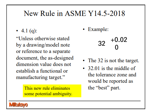
I know its the standard but I’m going to disagree with their wording. 32.01 would not necessarily be the “best”. By their first paragraph, they sort of imply that there is no “best”, or what I would call the target.
So why not just dimension it 32.01 ±0.01 and get rid of asymmetrical and unilateral in the standard if it doesn’t mean anything? To me it means something to engineering and anyone looking at the design what the optimal/designed values are.
Digging around some machinists forums on the topic, a lot seem to target that nominal value feeling it represents best fit. Some seemed to not care and just convert the dimension to a limit range. Same kinds of arguments as here.
I agree that the wording about “best” is not accurate. As far as tolerance on a drawing goes, it’s either good or no good.
As far as using asymmetric dimensioning, it’s for convenience of representation and communication of how things will work together. Particularly in metric designs, most things are designed nominally to integer mm dimensions. Asymmetric tolerances are an easy way to draw and communicate that the part is going to be undersize/oversize from the nominal to understand quickly what sort of tolerance to select for the mating part. It’s also inconvenient to draw/model to the midpoint of the tolerance band. This is especially true in an environment such as one-off equipment design where you may go from zero to 20 or more parts modeled, drawn, and issued for fab in a single day.