I am testing sw 2023 sp5 before installing it in our company.
I felt it was a release with a fewer bugs, but reading here and there about some annoyances I felt i need a place to list all the bugs I need to test against our workflows.
I am going to post 1 reply for every bug i encountered and the KB references I am aware of.
every other contribution is welcome!
SolidWorks 2023 SP5
Regression from SolidWorks 2023 SP4
Items with different file names that callout same item number combine and merge themselves into one item in the BOM, in SP5 they combine themselves but one of the item is not balloonable.
When the items are named differently and the configuration calls out the item number, the BOM comes up correctly but we are unable to balloon the culprit items. The balloons come out with an * rather then the item number they should call-out.
The work-around is to revert back to SP4.
It is still being analyzed. Will update when assigned an SPR.
Abstract : “Refresh cache during log in” fails to trigger on initial vault view login (after reboot) when login prompt is suppressed via “DisableAutoLoginPrompt” registry option
login from explorer with RMB does not trigger the local cache refresh.
login from pdm client icon (edmserver.exe) does trigger the refresh cache as expected.
BR10000369019 - ‘Add-in loading performance….’ warning message cannot stay hidden if turn off ‘Remind me when a document has not been saved for’ option in System Options.
I had users that disabled the pdm add-in by mistake due to the popup (which is completely unwanted and pops up in a absolutely negligible scenario)
One that I’ve run into a couple of times is doing an sketch extrude mid-plane, or extrude all both sides, only does one side as shown in the preview, and if you accept the solution the extrude is only one side.
If you change to a one directional extrude and then go back to the double ended extrude, it functions properly.
DESCRIPTION
Create a folder name “Cutlist Templates” under c:\temp
Tools->Options->File Locations->Weldment Cut List Templates and point the folder directory created in step 1. Ok
Open a drawing
Insert, Table, Cut List. Notice the default cut list template is not pointing to the assigned folder
CLOSURE INFORMATION
This issue is reported to Dassault Systèmes development team.
I thought it was supposed to be a new enhancement available from 2023…but the what is new mentions tranparent “bodies” not “components”
Assembly components are not displayed as transparent with See through transparent components in HLR/HLV enabled in HLR drawing view
Portfolio / Domain: SOLIDWORKS Desktop / E-Apps
Product: Drawings
OS: Windows 10 64 bits
Detected level(s): SOLIDWORKS 2023 SP3
Description
Assembly components are not displayed as transparent with See through
transparent components in HLR/HLV enabled in HLR drawing view
Closure Information
This issue is reported to Dassault Systèmes development team.
Another drawing related issue introduced with the new transparency option for views
BR Article: BR10000354471
Status: Opening transparency related problem (again: this was supposed to be a new enhancement in 2023!)
BR Drawing Template saved with option ‘See through transparent components in HLR/HLV’ disabled , doesnt remember the settings when used.
Portfolio / Domain: SOLIDWORKS Desktop / E-Apps
Product: Systems
OS: Windows 10 64 bits
Detected level(s): SOLIDWORKS 2023 SP2
Description
Steps to reproduce this issue : 1. Open a new drawing document in SW 2023.
2. Click Tools > Options > Document Properties > Detailing a. Disable ’ See
through transparent components in HLR/HLV '> Ok 3. Save this file as a new
drawing template. 4. Create a new drawing using the template saved in ‘step
3’ 5. Observed that the option ’ See through transparent components in
HLR/HLV ’ is enabled again.
Closure Information
This issue is reported to Dassault Systèmes development team.
Drawing templates do not save the new transparency setting or the new settings is not recognized by SW in document properties and new views are created with the transparent flag on and shown transparent in their 2D views.
STILL OPEN FROM SW2022SP5 REPRODUCED ON 2023SP5 AS WELL
workaround unbreak, remake balloons break again, but if you move the balloons they show an asterisk again.
BR Auto Balloon Balloons on a detail view disappear after the creation of a Broken Out Section View
Portfolio / Domain: SOLIDWORKS Desktop / E-Apps
Product: Drawings
OS: Windows 10 64 bits
Detected level(s): SOLIDWORKS 2022 SP5
DESCRIPTION
Within a SOLIDWORKS drawing the balloons on a detail view may disappear
when you create a Broken Out Section view to one of the parent views.
CLOSURE INFORMATION
This issue is reported to Dassault Systèmes development team.
Also balloon and detail view related
Balloons on the Detail view made from Section view disappear or become dangling if there is a Broken-out Section (BOS) on that Section view
Portfolio / Domain: SOLIDWORKS Desktop / E-Apps
Product: Drawings
OS: Windows 10 64 bits
Detected level(s): SOLIDWORKS 2023 SP0
Description
Open attached drawing 2. Annotations > Balloon 3. Attempt to place
Balloon on Detail View J on any edge 4. Notice Balloon disappears Problem
not reproducible if Broken Out Section view is deleted Same as SPR 1150111
Closure Information
This issue is reported to Dassault Systèmes development team.
you can “unbreak” the view and see if the balloons are hidden within it and if so move them out of the break. Doubt that’s the case but figured I’d point it out in case.
SW CRASH ON EDITING EXCEL DESIGN TABLES HOTFIX AVAILABLE
REPRODUCED ON EMPTY PART AND ASSY FILES WITH 2023 SP5
Design Table - Editing Design Table may cause SOLIDWORKS crash.
Portfolio / Domain: SOLIDWORKS Desktop / E-Apps
Product: Assemblies
OS: Windows 10 64 bits
Detected level(s): SOLIDWORKS 2023 SP4
Description
• Environment:
Tested and reproduced: SW2023SP3, SW2023SP4
Not reproducible: SW2022SP5, SW2023SP2.1
• Scenario1: (from scratch)
Create a new part.
Create a sketch and insert some sketch entities and smart dimensions.
RMB on Annotations > Show Feature Dimensions.
Insert > Tables > Excel Design Table
Double click on the dimensions to add them into Design Table.
• Scenario2: (existing files)
Open an existing file with a design table.
Edit the design table.
• Actual Result:
SOLIDWORKS crashes.
• Expected Result:
SOLIDWORKS should not crash during editing Design Table.
• Workarounds:
Not found.
Closure Information
This issue is non-reproducible in SOLIDWORKS Desktop 2024 SP0.1.
A HotFix for SOLIDWORKS Desktop 2023 SP5 are implemented.
Please refer to QA00000307226 for further instructions and how to get the HotFix.
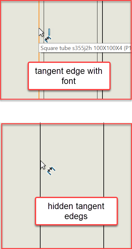
We just updated from sw22sp5 to sw23sp5 and faced first annoying issue:
If drawing view has tangent edges hidden, it’s impossible to dimension structural members. When you switch to tangent edges with font, you can dimension. Anyone else has this same behaviour?
EDIT:
Found fix SPR1254289
“workaround: In SW2022, it works if Options > Selection > Selection of hidden edges > ‘Allow selection in HLR and shaded mode’ option is selected”
BR10000367139: Insert > Part > Break link to original part - the Part Material of the child part replaces the that stored in the parent
The 2023 SP5 hotfix to address this issue is available in the attachment HotFix_HF-1210441_2023sp05.exe
If you place the “View from behind” command on the mouse gestures and select this command, the current view is adopted as the default view rather than being rotated to the view from behind.
The behavior is reproducible in 2024.
I am trying to reprogram the command with a small macro and then place this macro on the mouse gesture. I’ll report back if it works.
Solution:
The problem only occurs if you insert the command again from the command selection on a mouse gesture.
If, for example, you take the existing command from the 8-fold mouse gesture and move it to a position on the 4-fold mouse gesture, the command works as expected. ><
I saw this bug too, but limited to some model based on a verycold template. edges were not selectable, but switching from no tangent edges to tangent edges visualized solved the poblem. you can switch the viee back once dimensioned.
Exported STEP files may be invalid due to Windows region settings
Steps to reproduce:
Open Windows region settings
Set Format to English (United States)
Open Additional settings…
Under the Number tab set a new value for the Decimal symbol, like comma “,” or some other character (Windows allows up to three, but only the first one will be used) and click apply
Open a model in SOLIDWORKS and save as STEP (AP203 or AP214)
Inspect the STEP file with a text editor
Incorrectly formatted STEP file (decimal symbol set to comma):
Successfully reproduced using SOLIDWORKS 2023 SP5 on Windows 10 and 11.
If any other format is used, such as English (United Kingdom), it seems like the decimal symbol setting is ignored and the dot “.” will be used. So this is most likely to occur for those who prefer English (United States) as the OS language, but have customized it to follow local number formats.
BR10000347928 mentions this issue, but doesn’t include much details.