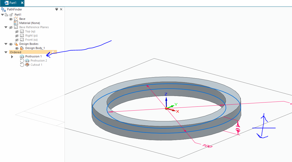
i was trying to design a cover for a thing and figured that it could maybe best be done via rotating 2 rings on the same axis (aka tilting the inner ring backwards to make the outer ring go downward relative to the inner ring…), but how do i do that in the program…
plus the rings could actually be the same object, the rotating axis might just give the perfect angles that i actually need… so the other solutions might even be more difficult to get the angle that i need…
or somehow just draw the same angles from 1 ring and then revolve the whole draft around the original 1 ring? (while the inner ring actually has to be only half of a ring to fit into the design properly…)
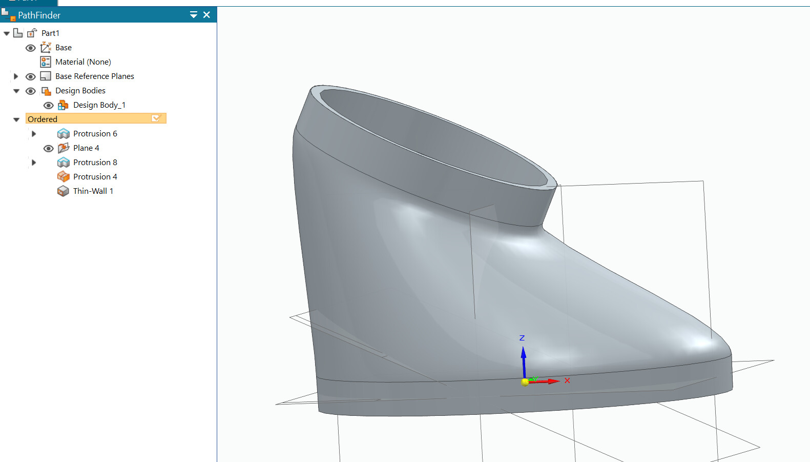
if you can point at the sides that i drew on my picture, then i could probably check what you drew, but my model is not supposed to have any flat surfaces (except on 1 side at the top; and the left side Fill probably creates the non-flat surface then).
altho it might actually be fixed, if the original cut cylinder would be at an angle itself then? but that would be the other point - how do i even mark all of these angles and cutouts on the model in the program and how do i fill the top part of your drawing for example… and then cut a smaller hole into that(which is probably the easiest part of the whole thing tho)…
or… it should probably even have quite flat edge in the bottom and then turns into an angled cylinder that i could then cut a hole into? but that hole would need to follow the somewhat flat edge in the bottom then…
and this:
i thought i already was talking about 3d and solid edge, so maybe you could try and get on the same level a bit (it is 2(or 1,5) rings on 1 axis)
Most of your questions have about 5% of the information we need to understand your problem. Being rude to those trying to help you is not going to get you the results you are looking for.
and because i’m not even sure how all of this stuff is supposed to be modeled in the app, i cant even draw the whole thing lol - the 1,5 rotated rings just seemed the easiest way to describe it…
Hmm … still hard to understand …
I think you will have easier to express your self if you use a paper + pen and upload photo from your phone.
Try to draw end result in somewhat isometric view.
(Personally I find it cumbersome to draw in paint.)
(* edit added something that maybe mimic your goal edit *)
You just failed to communicate in words and pictures.
You talk 3D but you sketched 2D.
You talk rings and sketch 2 rectangles.
Are you drawing in 4th dimensions?
Rings and axis and no flat surface?
And your sketch is rectangles?
Gonna need lots of imagination to see what you want.
Give us what you’re drinking or smoking.
That’ll help.
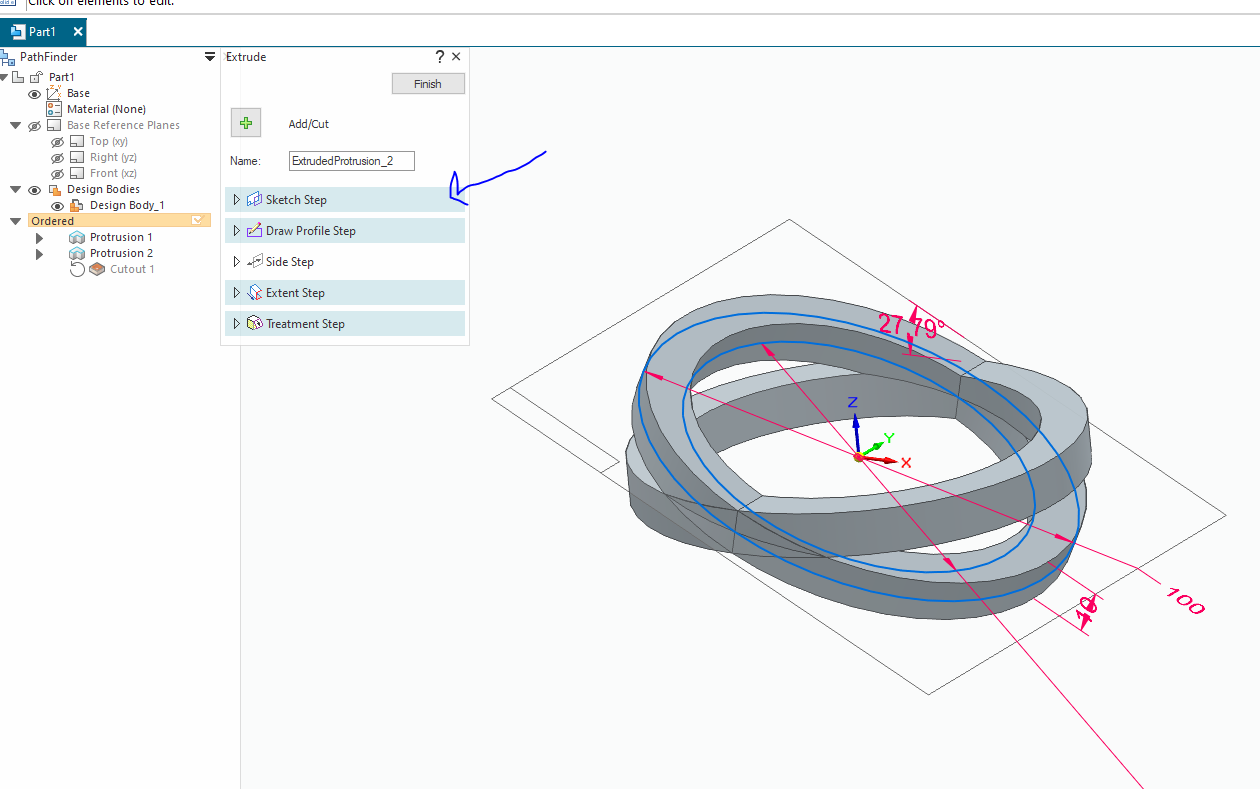
ok i try to draw it on paper, but your last image already has the 1 fixed axle removed, aka the 1,5 rings are not rotating on the same 1 axis, but have rather been pulled into separate “parallel” planes/faces with no common axis at all
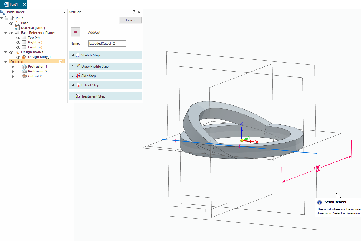
Another suggestion is to show us what you’ve gotten done so far. If you upload the part/assembly, or at least provide a screenshot it will be easier for us to see where you are struggling and make recommendations.
yes, something like that, but how do you even model something like this and then also fill in all of those gaps and add more angles, etc?
i probably still cant draw the thing itself, but the proportions+angles and theory should look something like this: https://www.upload.ee/image/17610146/cover1.jpg
it would actually add more features, if the bigger ring would stay rotating in several fixable steps, but i’m not really sure what would fill in all of those gaps then… but if i can get the angles kinda perfect, then it can all stay fixed and non-movable etc…