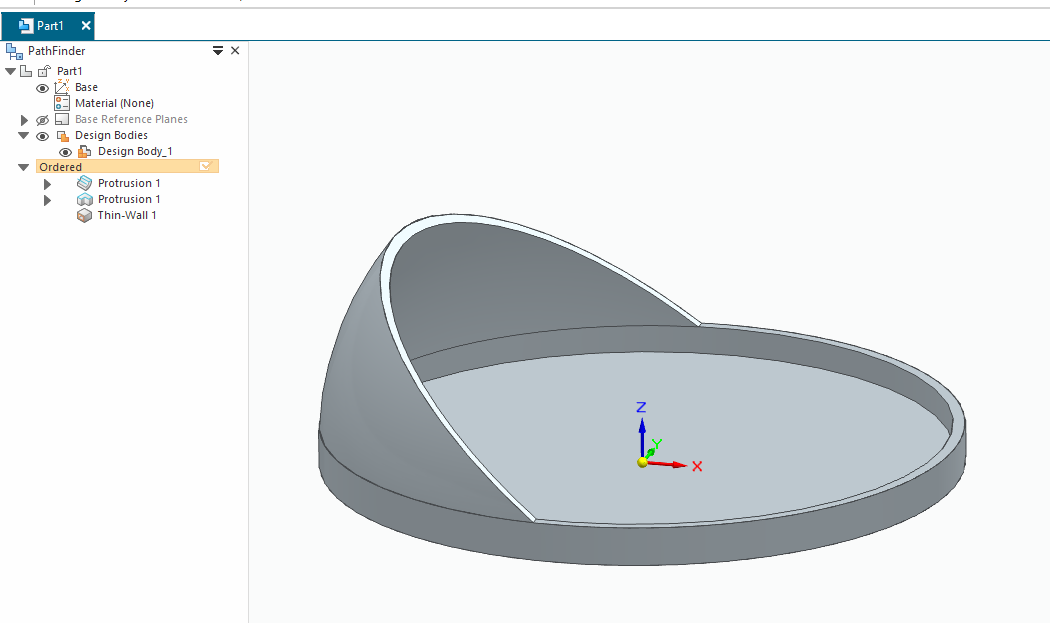
For total filled its only 2 features ..
image.png
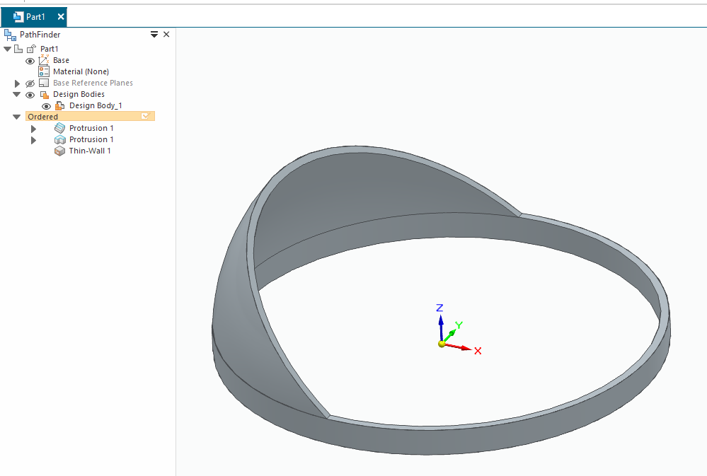
With an extra thinwall command you can “open up” face/faces.
image.png
well, it looks kinda similar, but if you flip your 2nd picture vertically, then you can see that the fill angle is not that good, because it just covers the whole enclosed area really weirdly, so i’m not even sure what is going on in there or how to fix/remodel that lol (on my theory pic the left fill area goes further away from the edge of the 1st inner ring, but this model seems to be the exact opposite in the other direction)
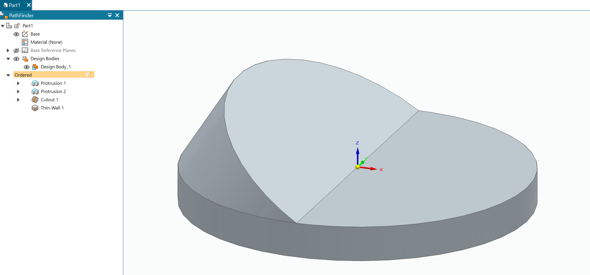
We’re domed!
Which one do you want?
2RingAxis-03.jpg
2RingAxis-04.jpg
Ai bot went into error mode again? it does seem to like to rotate half objects around the axis that it finally figured out tho, kinda like the fingers and left hands that it still haven’t figured out yet lol
Bah .. I’m sort of lost here ..
With thinwall you can open what surface you want …
image.png
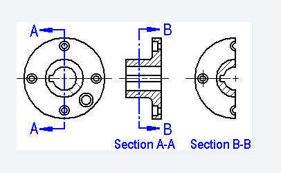
In you paper drawing can you change it to section view (in the center)..
Sort of ..
So maybe I get at better grip on what you want to do.
Or you can edit my attached file (SE comunity version)
cathemall.par (240 KB)
ok thanks i can try that, but maybe the whole fill issue is that the 1st inner ring has(should have) a smaller diameter than the outer rotating ring? so the filler area from the top of inner half ring has to(should) move outwards towards the bigger ring… altho i still dont have any clue how to model all of that stuff into 1 solid piece then…
Hmm still lost in the dark …
As already mention I would be helpfull if you can make section view of your idea in z-x plane and also z-y plane (take picture bellow as reference for axis).
image.png
Have moved the feature around to get this kind of “filler area” around the outer “ring”.
cathemall.par (250 KB)
ok thanks i try to check those, but now the inner ring seems to be smaller, but the filler should be going smoothly from the inner ring to the outer/bottom ring without any flat surfaces on the top… altho i dont even have a clue if that would even be possible at all…
and the tilted/cut cylinder thing i mentioned earlier would 1st look something like this?
https://www.upload.ee/image/17610694/cut1.jpg
and then it should be carved into the whole 2 rotating rings thingie… if it would even be possible to add the bottom ring to that tilted cylinder thingie…
The middle figure is a section view. This is what I meant when I asked that you should draw a section view of your idea.
the green is probably the section view then, the rest is just some thoughts about how this could be modeled from a rough block to get the actual shape and angles etc…
https://www.upload.ee/image/17610866/cut2.jpg
not sure about the bottom ring on the section view though, because it should be opened from the very bottom, but still goes around the whole thing in the bottom itself like a whole ring…
(PS. i probably cant open the community file)
You have posted many times and many people have tried to help you. You still have not provided a clear picture of what you want. Your sketches and written description have not done the job.
I will reiterate what has been suggested to you. Provide an isometric sketch or better yet, an image of something that is already shaped like what you want. You will get very good and clear help.

![]()
![]()
image.png
With its section view …
image.png
image.png
I assume that you have installed SE commuity verison of the software (after all you are hanging out in Solid Edge section of this cadforum) . So what version do you use ? (would be on the app icon and also on the splashscreen).
Another piece of the puzzle is an image on what object you want to make this cover for …
that probably looks quite nice, but can you make a video about how to build this stuff in the program? it’s probably just based on some basic functions, but it is not even possible to find any tutorial videos about this stuff, hence also the title of my previous topic…
I’m running out of space on my gdrive so it will be pictures instead.
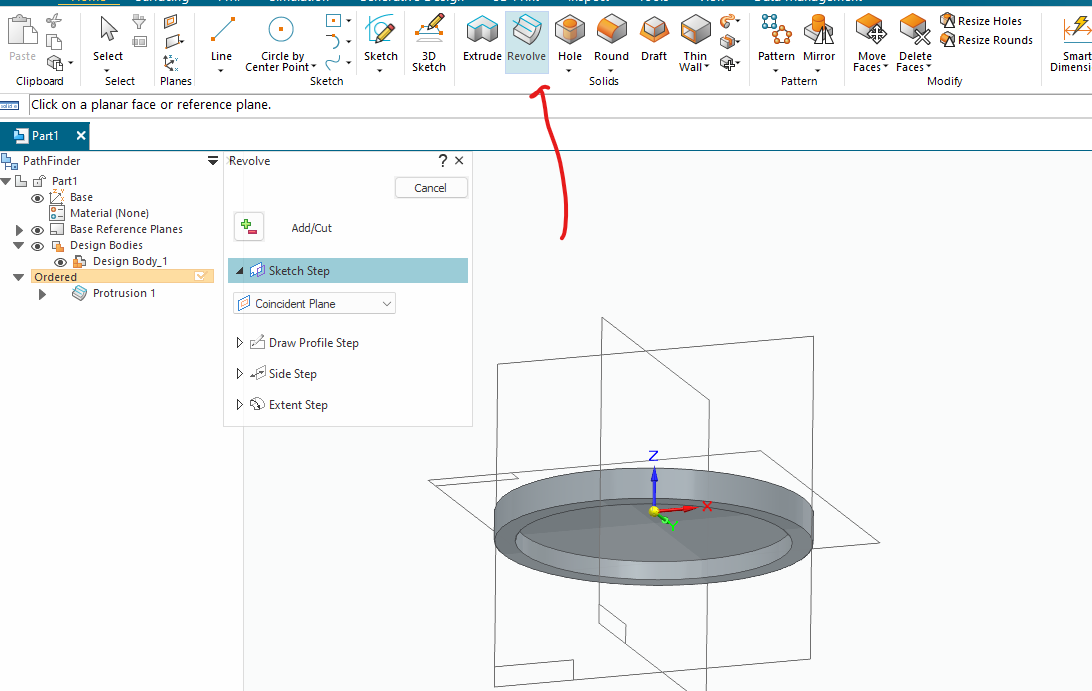
First an revolve with your profile ..
image.png
Axis of revolution around the center plane.
We end up with this (also marked the revolve button).
image.png
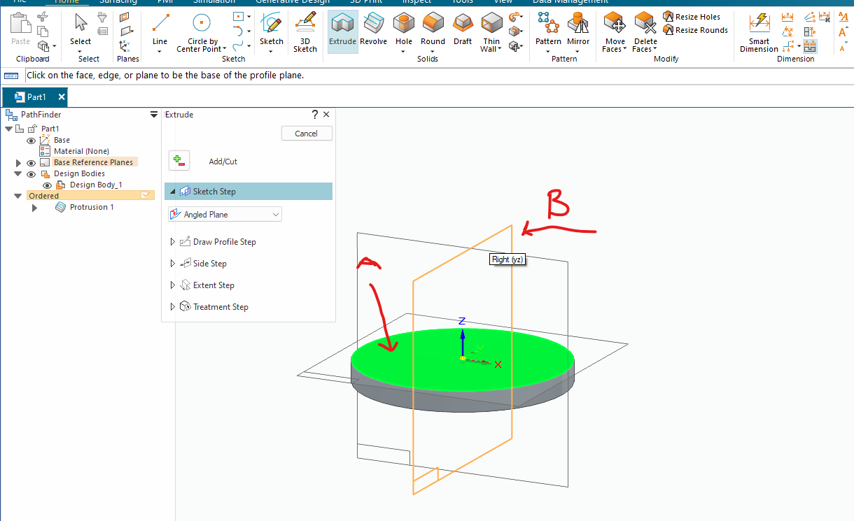
The we make a normal extrude but on an angeled plane ..
image.png
Pick top surface (A) on your profile and one intersected plane (B) (that you want to rotate the plane around).
image.png
Choose some angel.
image.png
Now we will be facing in its normal direction ..
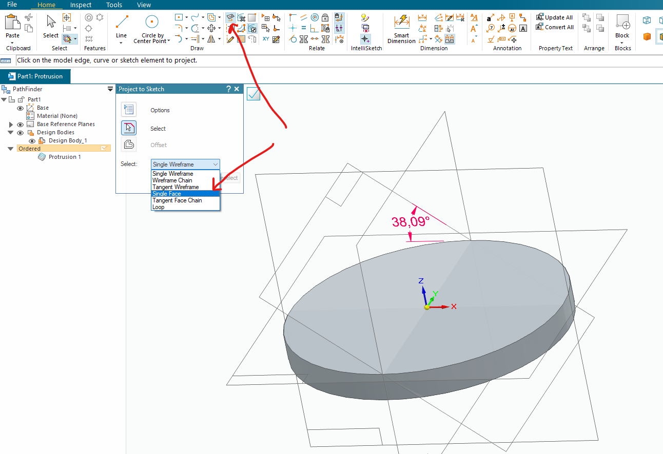
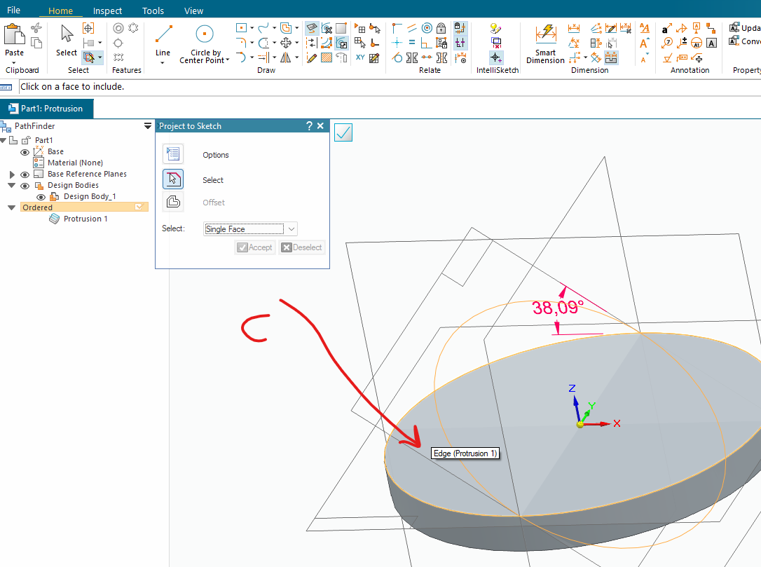
For better grip of what is what we rotate the model a bit and include (with “Project to sketch” command) the top surface of your already done model.
Select face (C) and press Accept.
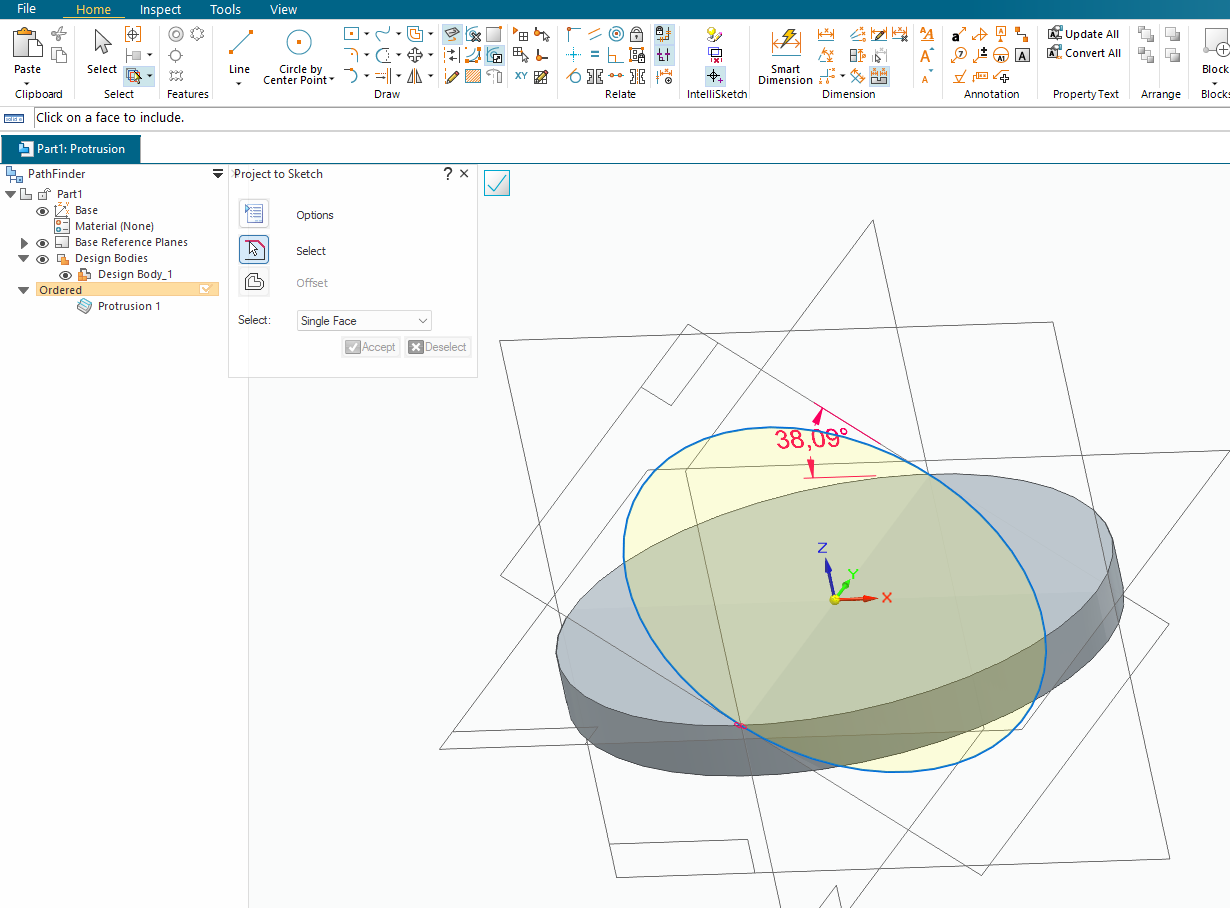
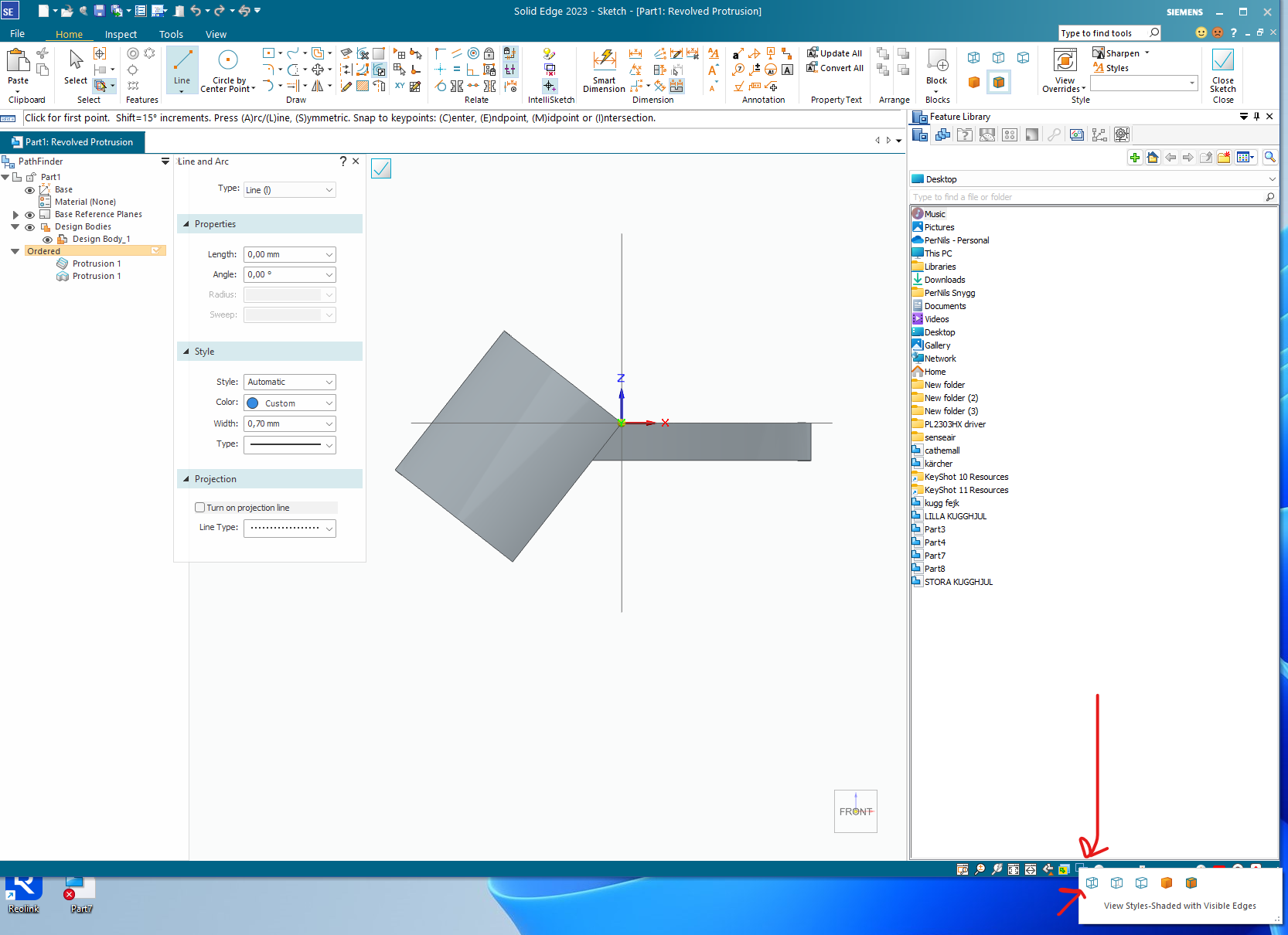
As we now want as your written many times 0,5 of a ring we must trim away half of it.
To get into the sketch views normal we press ctrl+h or click on the icon.
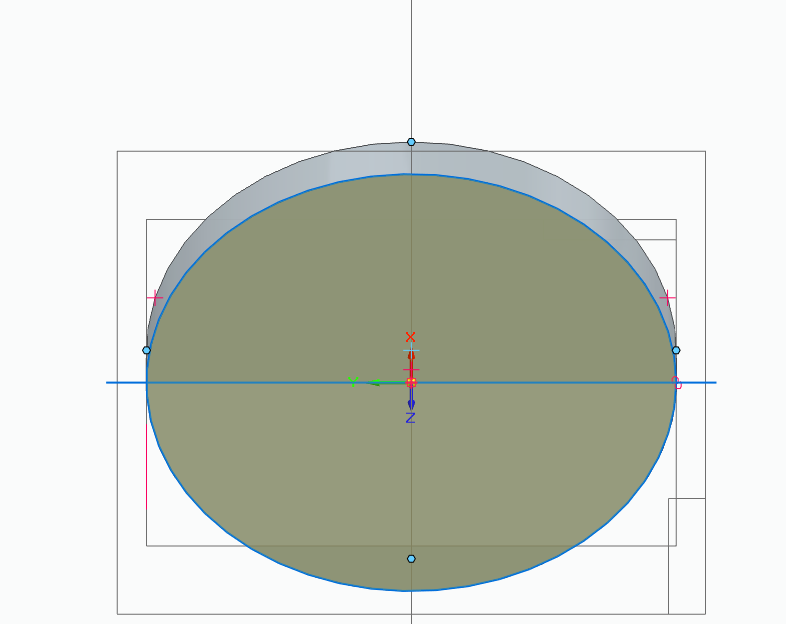
Now we draw a line it the center.
![]() continue on next post
continue on next post ![]()
image.png
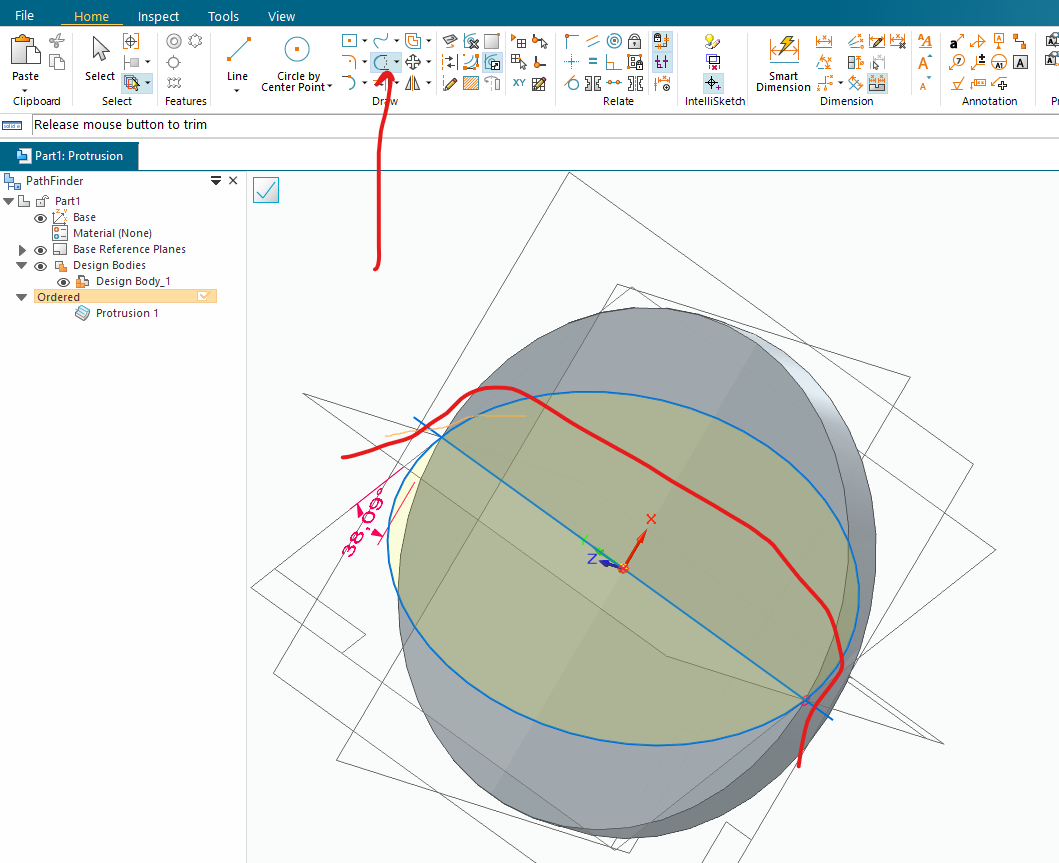
Rotate a bit just to get a more clear picture on what side of the circle to trim.
image.png
The red line is sort of how you move to trim away the unwanted parts.
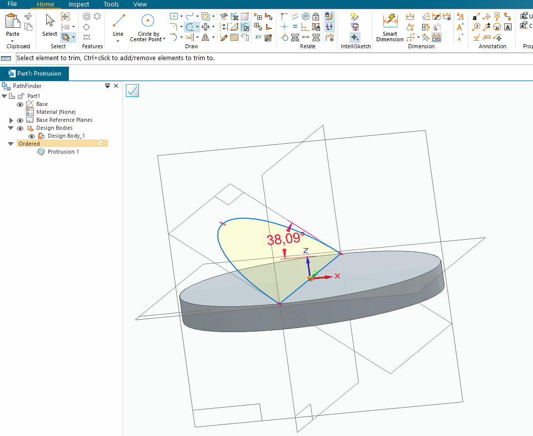
Your profile will then be ..
image.png
Just extrude it downwards a bit ..
{B57CA0AA-C2E7-4D46-A7C8-037B48FB91C4}.png
To remove the unwanted junk just use the revolve command again on the same plane as your base feature.
Change to wireframe mode ..
image.png
Draw or use “project to sketch” to trace the original grove. Use the same axis of rotation.
Set right direction for cut..
We have then now ..
But missing som on the bottom side ..
This can be fixed with “Thin wall command” .. just use the open Faces option and press the bottom surface.
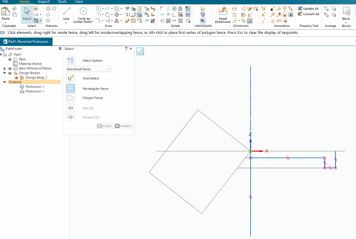
image.png
If you don’t want to have different wall thickness then you just start with a solid disc instead.
The workflow is the same.
Modelling is just to think what primitives I need to add or subtract to get what I want.
ok thanks i can try and see if i can mix all of this stuff into a model now, but already noticed 2 issues - 1st i probably solved myself by clicking the sketch view button, but the 2nd issue is that i dont even know how can i do the 1st Revolve step if the sketch does not touch the middle(X?) axis - aka if you want a hole on top of the 1st revolved model, it will not touch the center axis in the middle, so i dont even have a clue how to get all of those tool icons that are seen on the 1st picture to make it revolve around itself to create the model etc… - so the issue is basically the Revolve button not working by itself automatically or i dont even know how to set the Axis of revolution, because i dont know if it has to be in the “edit sketch” mode or when would the button even become active or start working etc…
and this is basically the whole issue with the whole thing - only really “small” details like this will get really confusing and it’s not even possible to find any tutorials about it, while the rest of the stuff like drawing and extruding etc itself is kinda easy and self explanatory etc…
altho after adding the new hole, would it complicate any of the other steps then, which do not have to count the hole in the middle atm?
With all due respect, you need to do some basic skills training. Your comment about not knowing how to make a revolve with a hole in it reveals that.
Please, before you go any further, stop and go through the built-in tutorials. They will be a tremendous help to you and rapidly develop your skill.