Hi,
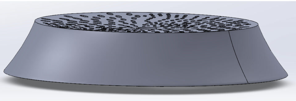
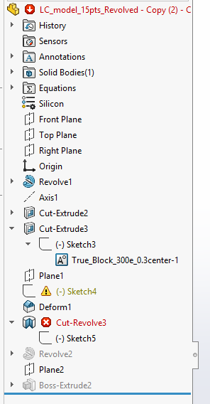
I am modeling a part that looks like this:
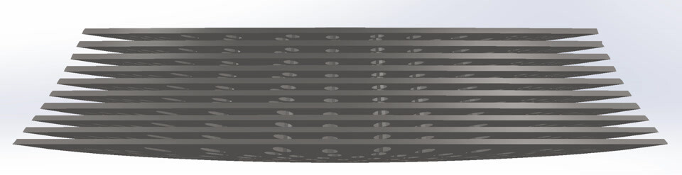
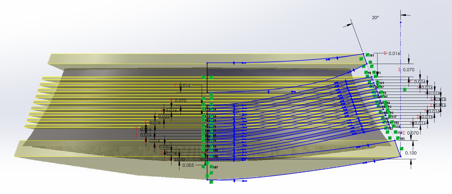
It is a disk with 300 ellipses cut through it. I need to slice it (with curved slices) like this:
The slices are all different sizes. This procedure works great, until I increase the curvature of the top and bottom faces (which I need to do)
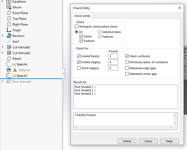
The issues I have been encountering:
- Invalid faces
- Invalid Geometry errors (likely caused by the slices hitting an edge of one of the elliptical holes, resulting in zero-thickness geometry)
The outer diameter of this model is about 0.38 mm (not sure if this would cause rounding errors with the holes)
I have attached a zip file of the part.
Thanks!
Your file did not come through. There is a 10MB limit on upload file size. If this file exceeds that, try zipping it to make it smaller. If it is still too big, extrude a solid block to consume all the geometry. If it’s still too big then let me know and I will temporarily increase the limit.
Extruding a solid block reduced the final compressed zip file size to 11.8 MB. If you could temporarily increase the limit, that would be great!
It also says “Sorry, new users can not upload attachments.”
If you have a Google drive, Onedrive, dropbox, etc., you could share the file from there and link it here.
The size limit is now 15MB and you should be able to attach it.
1 Like
Just an FYI, this was modeled in SW 2025.
@tdhobrock You may want to “save as” back to 2023 format for more opportunity for feedback here.
Gotcha, thanks for the heads up!
Oof. Biologic/organic parts in SOLIDWORKS. Never a good idea. I opened your model and did nothing but a CTRL-Q rebuild and the Deform feature already has an error.
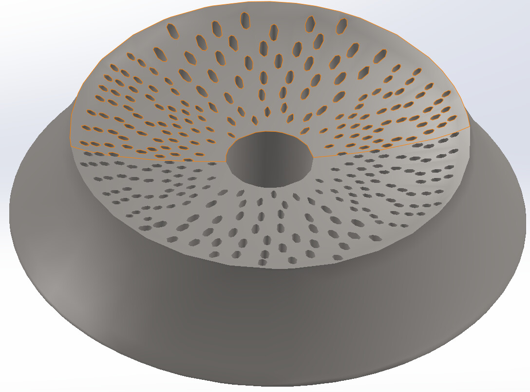
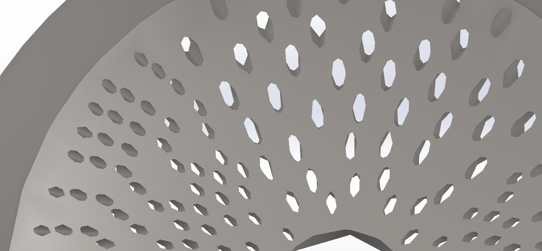
All bets are off after that. Don’t even try slicing it up until you have a clean model. Also, the ellipses are not ellipses. They are ellipse-like 9 sided polygons so instead of 300 faces, you have 2700 faces which are going to be much more computationally expensive and less accurate to deform.
Perhaps we should take a step back, as this seems like a bit of an X-Y Problem. What exactly is this thing and what is the purpose of deforming it?
2 Likes
Agreed. It’s a slight nightmare.
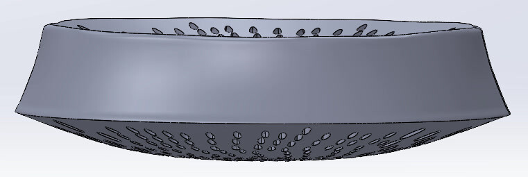
It is a biological model. I tried using ellipses on another version… it seemed like the edges were not defined:
In response to “What exactly is this thing and what is the purpose of deforming it?”
Simply speaking, it needs to widen toward the bottom and the elliptical cut outs need to follow that same outward curve. Now, I realize the simple solution would be to use a loft and then 300 lofted cutouts. However, I need to be able to slap several hundred different “sketch block” cutouts on the top to parameterize it for statistical FEA.
I’m very new to this organic realm of SolidWorks. Any suggestions? (different features other than deform?)
Does the cross section of the ellipse stay constant or will the ellipse ‘stretch’ like the main body does?
That doesn’t matter at this point. The stretching was just a biproduct of the deform.
It can stay constant if that will make this any easier
Are the ellipse holes randomly sized and spaced?
Not random, i have a python script that generates a .dxf file for them.
The code lets me chose the major and minor radius range, regional differences (top and bottom are larger and more elliptical than right an left regions), number of ellipses, and spacing
I would tackle this programmatically. A macro extracting the ellipse centers from your sketch and creating the appropriate path for a sweep. One plane, and two sketches per feature. Those 300 features would likely rebuild much faster than a deform and would be more robust.
Thank you for all of your help! I modified the Python script to also make a dxf file of the ellipse centers.
I will work on that macro. Am I understanding you right in saying the macro will draw the path for the swept cut for me?
If so, any good resources or starting points for writing this code