We receive step files of circuit boards (PCBA) from Altium. They look lovely. Everything is different colors and it looks real. Every component is made of a variety of bodies, for example, every surface mount resistor is 3 bodies. Do you have any suggestions for how to make it easier to get all these bodies combined so I don’t have a several thousand body part? Manually doing combines is taking a lot of time. Often, I encounter the dreaded “geometric condition” when I try to do a combine.
Can you upload an example? There may be options in Altium that affect the quality of the output as well.
Our electrical engineers set the parameters for the Altium STEP output, and the mechanical engineers request simple models. That way we avoid a lot of excess geometry. That is the easiest way to handle the problem, if you can get to whoever is making the files.
Dwight
3 Likes
I don’t know what your assemblies look like that will use these PCBs but we are struggling now with this very process. Altium boards are loaded up by their designers with vendor modeled components that have a lot of geometry detail. Saves them modeling time but kills us downstream. Our top controller assemblies and drawings are extrememly slow as a result. On the Altium side, they can remove small components and leave tall components, connectors, etc which helps, but even those components have more detail than we need.
The best of both worlds, in my opinion, is to export a dxf, import that in and extrude needed features. Then get a snapshot of the board from Altium and apply to both sides of the board as a decal. Still looks good and keeps geomtry simple.
2 Likes
Here’s an example I downloaded off Grabcad similar to what I see from our PCB designers, except our PCBs are 5 to 10 the size of this one. Extruded text and logos on components, sometimes surface bodies. It’s way too much work to try and simplify this, just easier to model it from scratch from their DXF files.
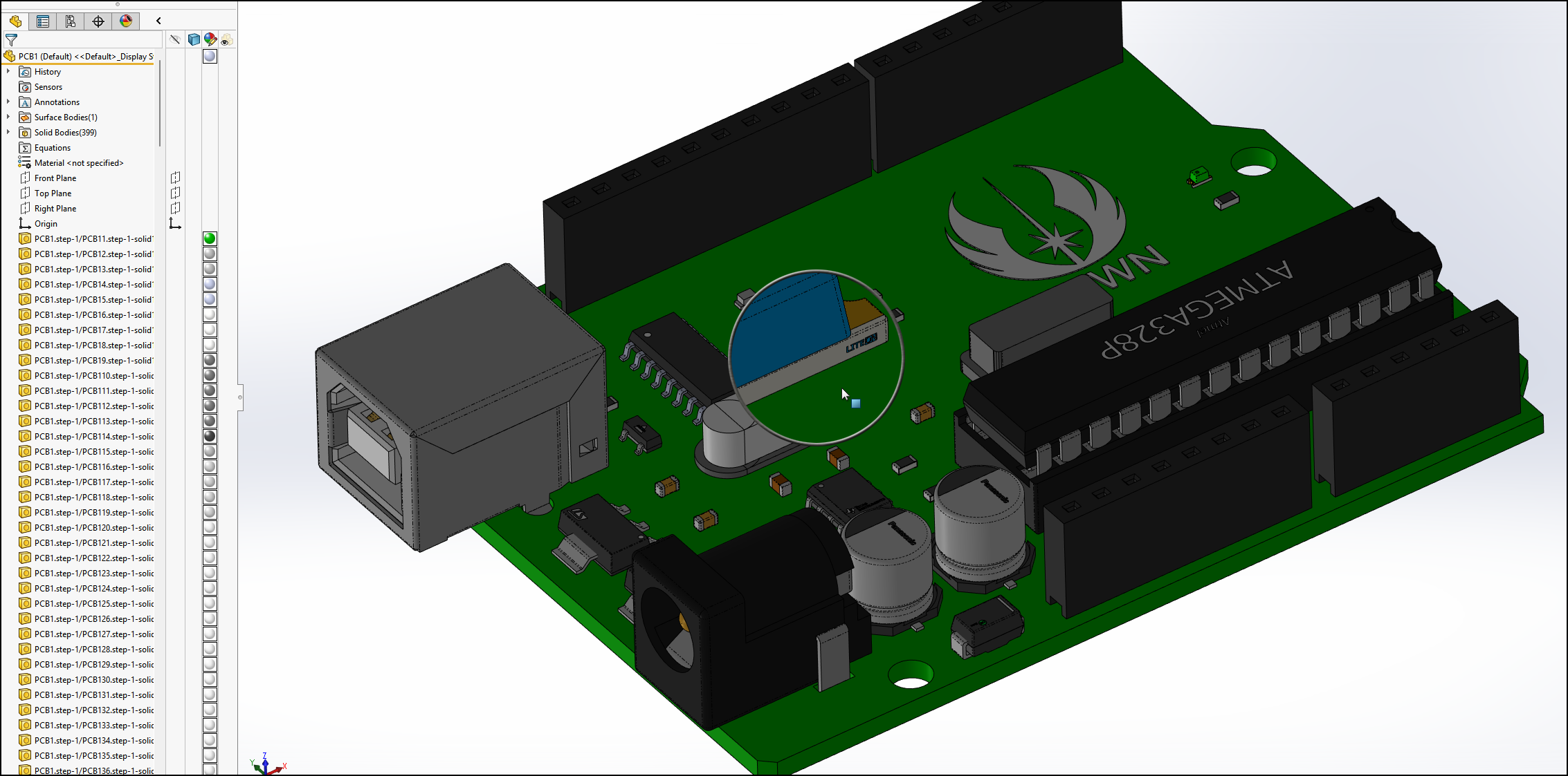
I removed the things that make this design recognizable for what it might do. There were several chips that had individual bodies for each lead. I take the STEP file and do a save as part. That’s what this file is.
For designs done in Allegro, we get IDF files (EMN/EMP) where the components are just blocks. It’s not as pretty, but doesn’t bog us down. I just need something that will let me do a very thorough fit check and will look good enough in the assembly drawings for the people putting it together.
Hopefully, this links to the file.
I am concerned about removing the small components. If the components aren’t there, I may think that there is an empty space when it actually isn’t. We are trying to see if we can make Altium’s CoDesigner work for us, but we only have PDM standard. That will end up with an assembly with many components. So far, we have only tried it on a board with a couple of LEDs and a connector.
Would an envelope help here? (I don’t have any experience with envelopes.)
Why would the absence of small components matter in board placement in your SolidWorks assemblies? As long as you show tall/big components, you should be covered in any interference checks.
If you really must combine them, you have to select them and use the combine feature (time consuming. Regardining the Altium, the reason some of the components like resistors are 3 bodies instead of one is the way Altium does 3d modeling, its tools just do simple modeling and doesen’t seem to join them, they are just a block of bodies. I had our Altium designer change to using SolidWorks to model his board components, then import them into his Altium library. Then on STEP export back to SolidWorks, its one body per component.
Would getting an IDF export from Altium be any kind of improvement? We’ve started doing this, pretty much the only components that I have detailed models set up for are connectors, then everything else just being blocks is okay.
If you want to stick with STEP / Parasolid then you’ll have to provide the Altium library with some updated and simplified models.
1 Like
Don’t know if it’s true for Carrie but I need all the small parts on there for checking clearances where I run EMI shielding walls around the surface of PCBAs.
1 Like
would using the freeze bar on this component help out with the speed of the upstream assemblies and drawings where you use this. Once this has been converted with any of the needed routing points for electrical and any other mate references it should not change. I once took a part that took 5 min to open and froze it and then it would open in seconds. Getting it finalized for freezing was the hard part.
2 Likes
If only opening was the problem. The cabinet assembly, which has about a 1000 total components (not including all the PCBs multi bodies) loads fairly quick. Little over 1 and a half minutes lightweight. Around 4 minutes fully loaded which could be improved with some sub-assembly simplification.
The real issue is the assembly drawing, 20-30 minutes to save. I’m testing still but suspect its the PCBs detail and vendor electric components that have so much needless detail.
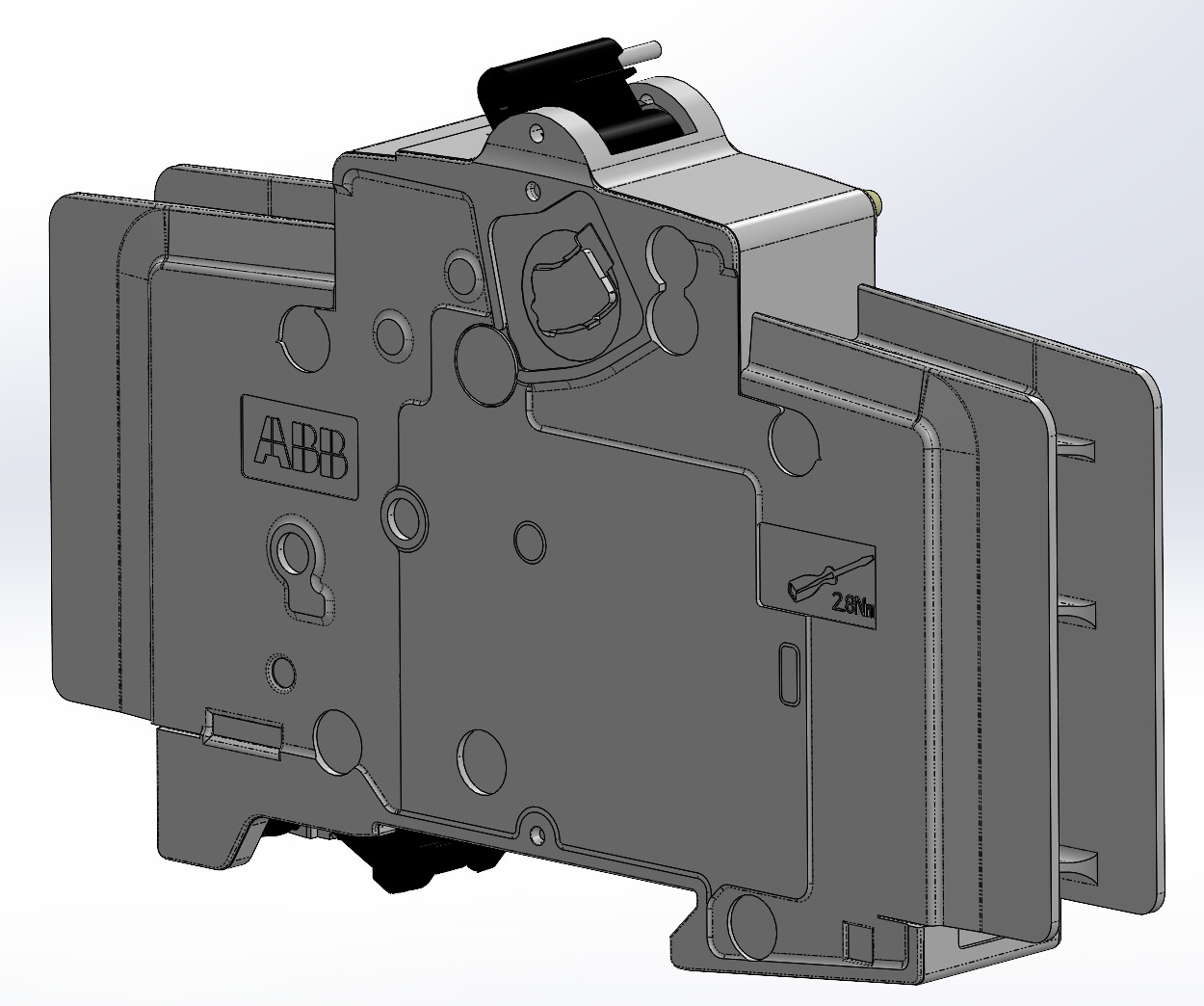
Here’s an example of a downloaded vendor part with too much detail, extruded text and a screwdriver logo.Pattern about 10 of these and 50 terminal blocks with similar detail, pretty sure the drawing is struggling because of it.
1 Like
thanks for the reminder to freeze all those parts. Some of them download parts are very detailed.
Big problem with downloaded vendor parts is they are dumb solids, no features to freeze.
I’ve tried simplify this part by deleting faces and fillets but it’s so much work I’m thinking remodel is faster. Then there are the lost matea and relations to contend with which is not easy in a global environment
We have the same issue with drawings containing components that have been imported. The imported components will generally have a lot of geometry errors, even if there are no errors showing in the feature tree. Using Check Entity (Tools | Evaluate | Check) will show these up. Depending on where these errors are when used in a drawing it can case the view to be forced to Draft Quality with increases the file size substantially.
I receive Altium step files and also (occasionally) use the CoDesigner add-in to pull designs from Altium 365. Both routes result in corrupted geometry that bogs SolidWorks down. I have two methods to improve system performance.
-
Import the step file into Rhino (V5!) and weed out any unnecessary geometry - labels, screens, infinite weenie components, moving them into a separate layer that I hide. Once I have decontented the model enough I export as STEP and import into Solidworks. Obvious problems are that this is no longer the original data, some corruption will survive and that there is the possibility of hiding a component that will cause an interference when parts get made. Done that…
-
Import the step file as a part (however long that takes), run the defeature tool to remove small components and holes and save the resultant as a part file. This will remove small bodies to a size you specify and simplify what’s left, which is great but will leave bits of component on the reverse side of the board as separate bodies. I find the geometry of the defeatured file much improved but the odd error will get through and it still doesn’t solve the component clash problem for you.
1 Like
Everytime I try defeature on these, I come to conclusion that its faster to manually model the simplfied PCB from scratch the way we need it. I do notice that defeature works better with an assembly than multibody part.
I ran into this issue recently. I tried the defeature tool but it just froze my session for hours and didn’t do anything.
So, I and ended up spending a day writing a macro that:
- Imports the .x_t file
- Saves each sub-assembly as a part
- Attempts to combine bodies in that part to as few as possible
- Replaces the sub-assembly with the saved part
- Adds additional information to the newly inserted part’s name (mfr. pn)
- Ultimately saves assembly as a part
The overall goal was to keep each component as its own body but have as few bodies as possible as well. Naming convention for parts needed to be preserved.
If this sounds useful, I can see if I can get it uploaded at some point
4 Likes
That sounds extremely useful! Would be very interested to have a go with it if it’s possible to share please.
2 Likes