Do anyone have experience/great success in creating or using Z-up template in SOLIDWORKS?
Even though SOLIDWORKS 2020 above have the option of Apply Z-up views, that only affect the view but not the Horizontal and Vertical (So when sketching, trying to place a horizontal relation will ended up with a vertical line…)
I have been looking at creating a Z-up template with “correct H and V” but the only workaround i ended up with involved several derived reference plane (which involve rotating the default plane to get the correct the H and V…) and result in a rather confusing feature tree
image.png
(I understand that it is possible to hide the obs plane from the feature tree using system option since they are the default plane but unfortunately i don’t want to do so as i would still like to use Y-up template which rely on the default plane in other scenario)
We tried desperately when we started in SW (2019) mostly because the rest of the 3D world has Z up, so importing our SE models they all came in standing on their face. But is was all in vain, there were a bunch of leads, two or three IIRC looked like they were going to be solutions and we would get all excited only to find out the work arounds were worse than having Z forward.
We gave up and just have a mess of models both ways now. Drawing views are a best guess, and the view orientation shortcut keys are frustratingly useless sometimes when working on a model who’s logical up is on the front view.
It would still be a workaround, I think - but at least you can define your coordinate system & use basically everything from it (planes, axis, point)…
It will be a big deal for us because it will make importing only for CNC purposes SO much better.
Plus you can then link all kinds of stuff to that new coordinate system properly (patterns, appearances, offsets, you name it) & any change to that coordinate system will ‘trickle down’ if set up properly which is huge for a history based CAD program, I think.
I’ve gave up on trying to achieve this years ago. Not worth fighting the tool over and less effort to just deal with the choices the devs made decades ago. Even if you get Z-up, at some point you want to render, or use environment lighting, or …, and then you have ground appearances over your left shoulder, or who knows what.
You can create a coordinate system that has your preferred “Z-up” and any exports you do can be relative to that coordinate system. There may even be export macros out there that automate this. Or you can use the “rotate” functionality of the move-copy body at the end of your feature tree (or at the beginning if you need to re-orient imported geometry).
I prefer the coordinate system approach. That keeps me from being tempted to introduce a configuration for an in-the-weeds implementation detail. For a simple part, I don’t like having a feature whose suppression state may royally muck up a drawing. Here’s a simple example. Add a Z-up coordinate system, and then in the parasolid save-as export options, select that coordinate system.
You could even put a Z-up coordinate system in your templates, if that saves a few clicks.
Export using Output Coordinate System.png
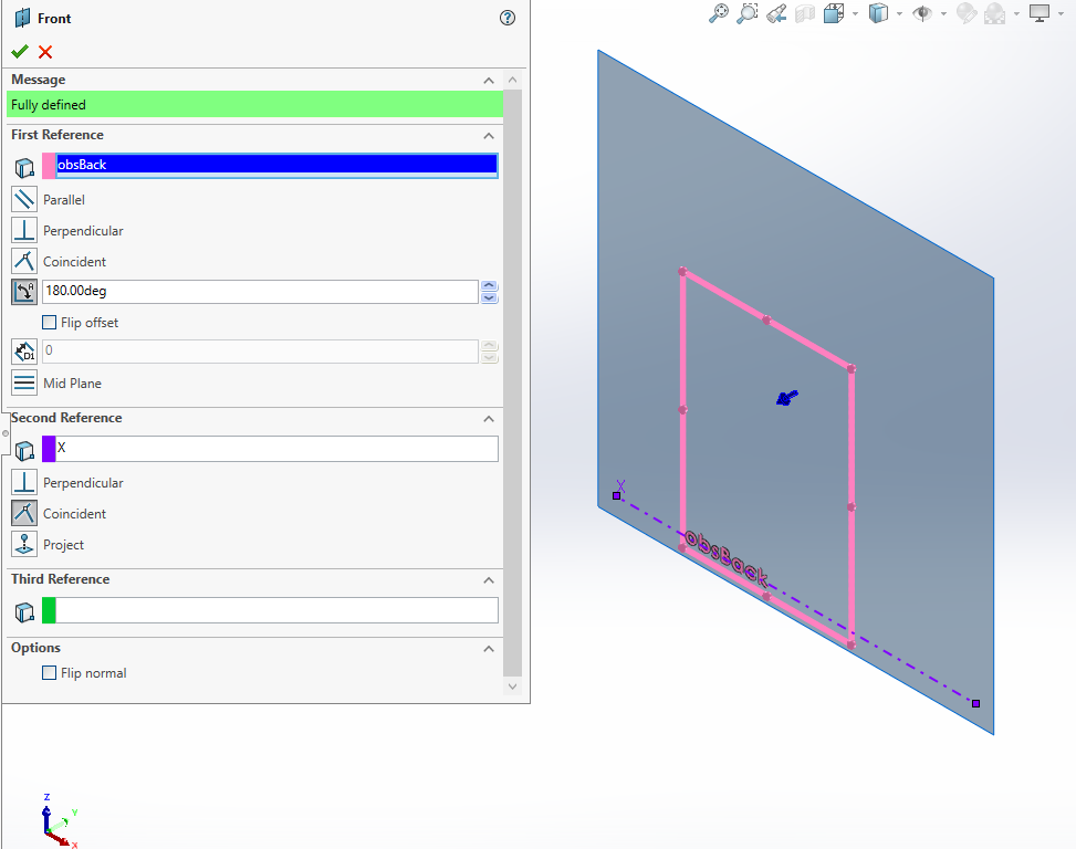
The Z+ being down is really annoying. The only workaround (beside accepting that) that i found is to create my own Front plane (by flipping the original ZX plane 180 deg so that Z is up..), this ensure that Z+ is being up, making things much easier especially when normal to sketch
image.png
Unfortunately, renaming the plane and view is not sufficient. The sketch vertical and horizontal relation is not converted properly
Thanks for the input! The lightning and rendering never cross my mind since i rarely render stuff.
Horiz and vert depends on the sketch x y.
You can make all sketches line up properly when you create them.
Or just ignore them like I do.
When I sketch a line, SW usually suggest the correct hori or vert one to use.