Fillet in 2d drawing before Extrude Boss
With draft angle, the result is different. In the first cases, the filleted edges are collimating. While in the second option, ther are parallel.
I am wondering which is better design for injection molded parts and why.
In general, it is best practice to avoid fillets in feature sketches. You may need to remove the fillet for some reason, such as applying dimensions, applying draft to a face, referencing an edge, you may want to make a fancy type of fillet, or make fillets intersect in a specific way.
Of course there are times when you need to put the fillet in the sketch, but those times are comparatively rare, and I’m not sure I could name them.
The result is only different if you draft in the extrude feature.
If you extrude, round, then draft it is the same. However, without the issues with a fillet in the sketch.
I am not sure it matters for injection molded parts as long as you follow the other rules about wall thickness ect. You can ask your tool shop if they have a preference.
When the draft is in a direction different from the extrude, or the draft has to be applied as a separate feature, fillets in the sketch and fillets before the shell generally hurt the chances of draft working.
You have to think of Draft, Fillet and Shell as being like a Rock, Paper, Scissors game. Generally speaking, you want Draft first, then outside fillets parallel to the direction of pull of the plastic part, then shell, then outside fillets normal to the direction of pull, and whatever edges inside the shell need filleting.
But frequently you have to break these rules. It depends very much on the complexity of your part and the size of the fillet vs the size of the shell.
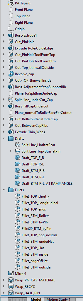
edit for TLDR: Near the end, just after drafts, before the mirror body.
This has been recent topic in our workplace. Because we live in a history-based modeling environment (many do not) I choose to embrace the history and think of a model as a “program” that generates the model. When fillets and drafts as well as mirror features are sprinkled throughout the feature tree with no thought or plan making edits to features made up stream can be difficult to decipher because later features nullified the intent of the earlier feature. This is why history free modeling is popular. Continuing with extrude and cut features after drafts and fillets have been applied just continue to make more and more tiny faces that just don’t like to heal, especially when using direct editing tools. This is why I put all the drafts after the end of all the features, then fillets, then the mirror body for symmetric part, then the wrap sketch features for date pin, part number, material code, etc.
As Matt has said, there are times when this must be broken, but I’ve found keeping to this guideline will help more often than not.
I often have a set of draft and round as the last thing before the shell. Then another set at the very end of the model. I find it easier than drafting both sides of an outside wall.
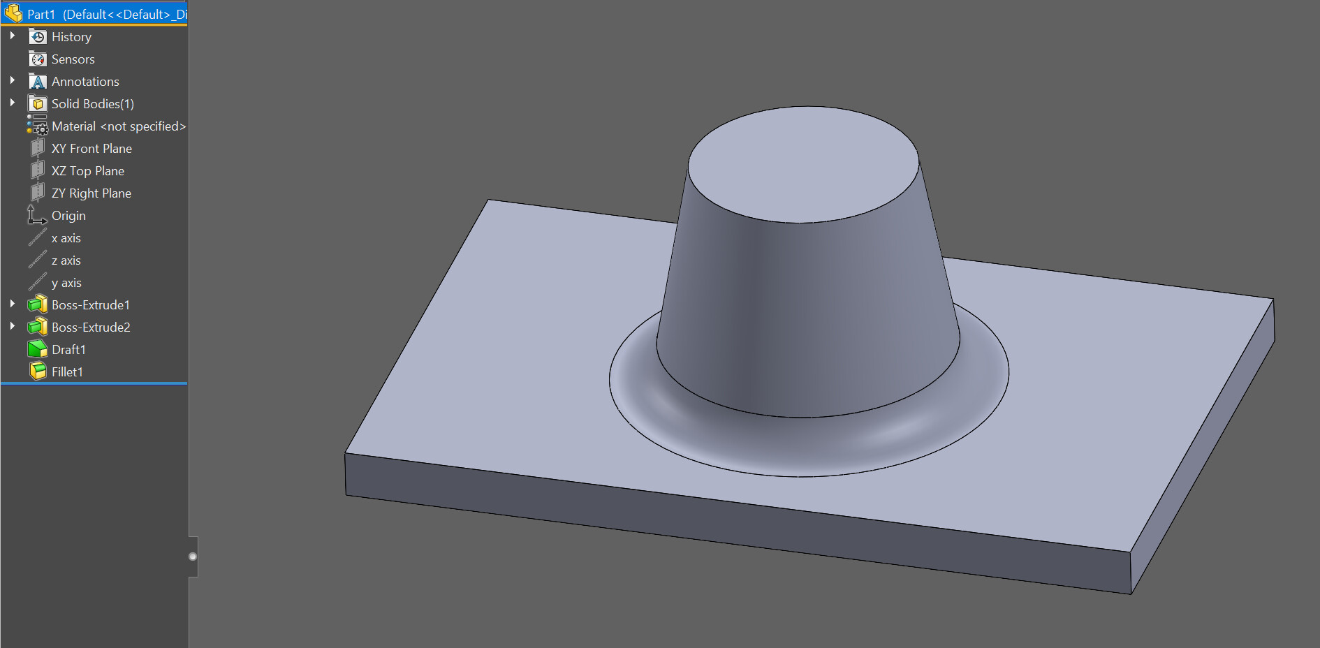
In summary, Extrude → draft → fillet is most prefered desgn for maximum editability. This results in identical fillet radius on the top and bottom faces. For tool maker, however, I believe not so convinient to mill this mold?
Left one is the prefered Extrude–Draft–Fillet. Right one is Extrude–Fillet–Draft.
I think right design is easier to make a mold using tapered mill.
Picture1.png
This really only applies if you have a very academic simple part where the sides are all straight like that. As far as overall plastic parts go, that’s not the majority. For molds, the machinist isn’t making faces with a single straight cut on a 3 axis machine.
Plus, many designers use non-single radius fillets, which have to be cut with surface machining anyway.
We work in a very similar fashion, though we try to have as many fillets as we can have together in one body before we have to split our main body into multiple ones(which happens before the mirror in general).
There are rare occurences, where we will priviledge having it done in a sketch, but they are for very specific cases as Matt said. I know off the top off my head, some edges do not handle well filets.
The age old chicken before the egg.
Whether your intent is mech or mold related, you setup your faces for the best shape control coupled with fillets (eggs).
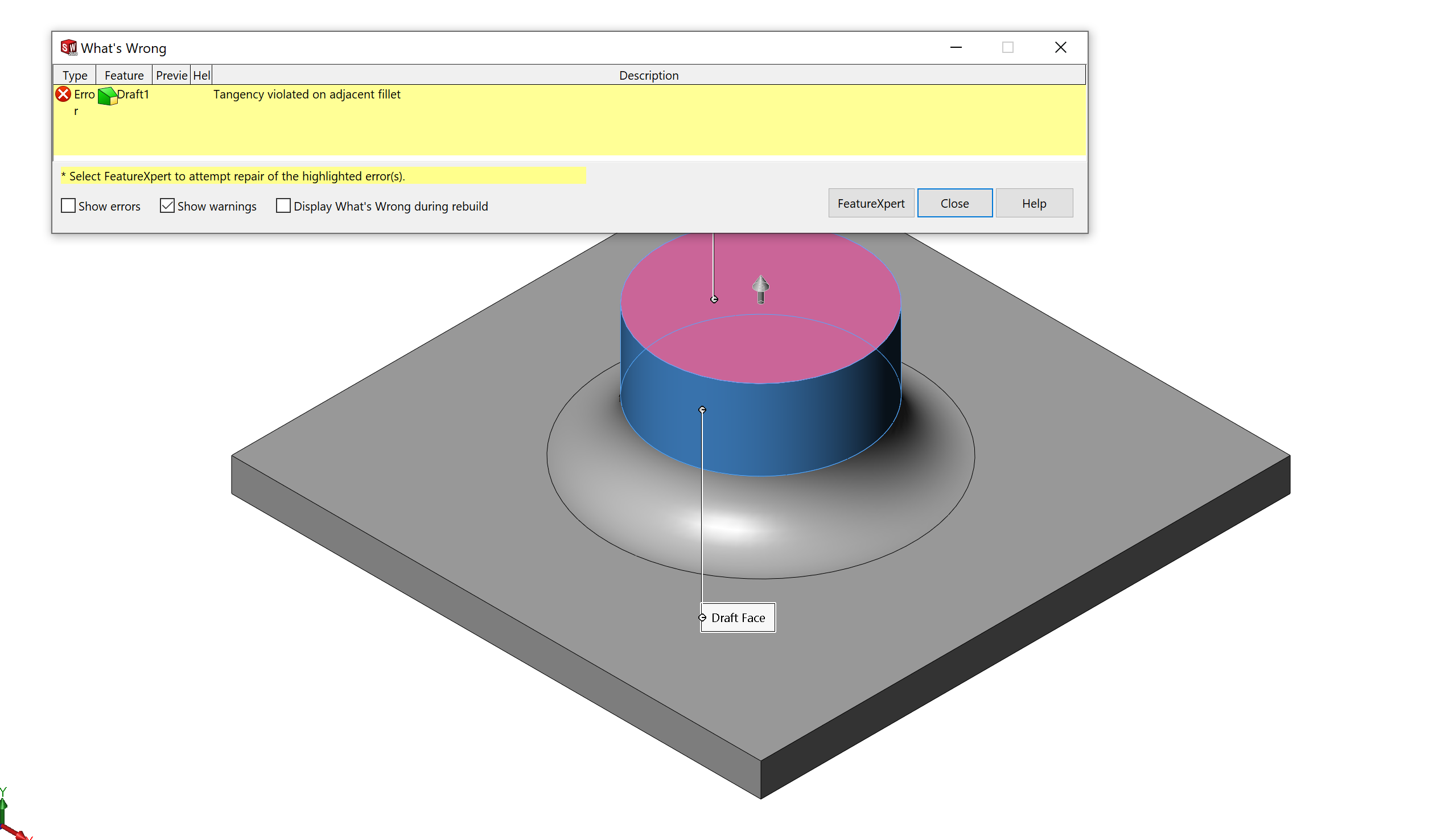
you can’t draft after the round. by definition a round is tangent to the adjacent faces but drafting changes that surface so the software won’t let you draft.
I am not sure if there is a better way to reference it but the 9th post has a picture of the geometry from the original problem. The rounds he wants to draft are on the sides not the top or bottom.