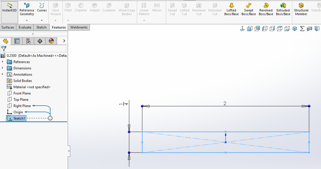
I attached a sample Part in which I created plate using the Structural Member function instead of doing it with an Extruded Boss/Base. By doing this the cut list properties for Plate are generated automatically by the software just like they are for Square Tubing, Channel, W-sections, etc., which saves a great deal of time. There’s an example of a .sldlfp sketch below.
image.png
I have a different .sldlfp file for each common thickness, along with a few that I created for a specific project. It wouldn’t be practical to have a file for every possible width, so I made all mine 2" wide. After creating the plate using the weldment feature I edit the sketch that’s absorbed in the feature to match the width I want. The sketches from the .sldlfp file are copied to the Part when used for Structural Members, but the Part file doesn’t maintain a link back to the .sldlfp file, so you can edit the sketches in the Part without affecting the .sldlfp file.
The Description property is linked to the dimensions, so it will update to match the edit.
If you want the thickness or width driven by other features in the model you can edit the sketch, make the width dimension driven, and then use relations to fully define the sketch. (Deleting the dimension instead of making it driven would mess up the property.)
I also attached one of my .sldlfp files. You can modify it to suit if you like, or use it as a template to create other thicknesses. As I said above, I just edit the sketch in the Part to get the desired width, but if you have a common size you use often I’d recommend making a .sldlfp file specifically for it so you won’t need to edit the sketch in the Part every time.
You could of course create a single file with configurations if you prefer that workflow, or if you have widths you use often you could have a separate .sldlfp file for each thickness, with a configurations for each width.
This technique also works well for other non-traditional shapes, like lumber, rebar, wire, etc.
0.7500.SLDLFP (47.3 KB)