I sometimes get tripped up by right-clicking the relation, which doesn’t work. To be clear, you have to right-click a sketch element in the pattern, not the pattern relation icon.
Dwight
I sometimes get tripped up by right-clicking the relation, which doesn’t work. To be clear, you have to right-click a sketch element in the pattern, not the pattern relation icon.
Dwight
I found a trick a while ago that I’ve used a few times. I know we can only break extension leaders around other dimensions, but I figured out a way to get it done if I need to break them around other leaders (notes, weld symbols, etc). I place the other annotation, then add a dimension that I really don’t need, with it’s extension line crossing the extension line of the one I want to break, at the location I want it to break.
image.png
Set the original dimension to break extension lines, then hide the new one. The break will stay there, even with the dimension it’s breaking around hidden.
image.png
If someone unfamiliar with this opens the drawing later they might have a lot of fun figuring out what’s going on. That’s just a bonus.
Perfect!
![]() ><
><
I would argue that there is always a solution that doesn’t require this, requires less work and doesn’t evoke hatred in future generations.
Also, I hate your drawings. Nothing personal. They just rub me the wrong way. Mixed case and periods at the end of annotations? I need eye bleach.
That’s fair. I don’t always use periods, unless the note is a complete sentence.
And I hate all caps. It always looks like shouting. I know it’s widely regarded as the best practice, but I still don’t like it, and in 13 years I haven’t received any complaints about it from clients or suppliers.
By the way, I dimension to hidden lines also. I’d like to see how the people who made that rule would show rebar placement in concrete.
I agree. I am constantly shouting in my head at work because we use all caps. And it’s annoying if you write somebody a text message with all caps on. It’s like forgetting to take the ear plugs out and SHOUT!
I’m just writing what they are all thinking. ![]()
By the way, I dimension to hidden lines also. I’d like to see how the people who made that rule would show rebar placement in concrete.
Section views. Or by flipping the script and showing the rebar as solid and the surrounding concrete as phantom/hidden.
image.png
But these are large projects where they are probably using a dedicated tool for that kind of thing. SW doesn’t do well with lots of detail and section views, so your approach is probably for the best.
Doing assembly cut “up to surface”.
This one is hidden unless you know the trick for parts: double clicking on a surface will select the end condition of “up to surface”. I don’t think this is technically supported because there is no formal item in end condition dropdown menu. Double click on the surface you want to cut up to while editing an assembly cut extrude. Just like it works for parts, it will convert the assembly extrude cut to “up to surface”. The end condition dropdown menu will be blank but the feature will still succeed. (if you close and reopen the feature then “up to surface” is available in the dropdown)
Not mine, but [mention]Alin[/mention]'s.
https://www.youtube.com/watch?v=eOGt3mwG0D4
Yes, my drawings don’t scream. No ALL CAPS !!!
Hidden line dimension. Only when necessary.
Of course, use a view with more visible lines.
[quote=“Glenn Schroeder” post_id=23362 time=1664540760 user_id=50]
Not mine, but @Alin’s.
https://www.youtube.com/watch?v=eOGt3mwG0D4
[/quote]
Not mine, but [mention]matt[/mention] 's . ![]() It is in the Bible.
It is in the Bible. ![]()
All caps is ASME Y14.100, a standard used by many in the US. Nothing about shouting.
Dwight
[quote=“Glenn Schroeder” post_id=23362 time=1664540760 user_id=50]
Not mine, but @Alin’s.
https://www.youtube.com/watch?v=eOGt3mwG0D4
[/quote]
Interesting… How is this different from using convert entity on face and trim it?
Interesting that the sketch symbol that SolidWorks is using is not actually the convert entities one - but the offset entities symbol.
It’s the same, just a little quicker.
SW isn’t using a different function (offset vs convert). The difference is between selecting a face vs selecting edges and converting them. Somehow that “convert” operation remembers its source entity and will always convert all edges of that same face, even if the original edges go away. If you select edges and convert them, then the edges go away, the constraint gets lost. It just depends on what you select to convert.
Yes. The usual issue is that it might add new edges disjointed from the sketch and preventing an extrude. They may also be out of sight, far away from the original sketch, making it tough to diagnose the problem unless you remember to expect this sort of thing.
Dwight
I learned something new on the Swamp today: https://r1132100503382-eu1-3dswym.3dexperience.3ds.com/#community:yUw32GbYTEqKdgY7-jbZPg/iquestion:eW0e_wmMQ6OHS2KgZcL0CQ. Thanks dave.laban.
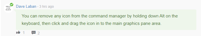
I always forget what key to hold down since I don’t have to move/re-move buttons often. It’s easier to remember to just go into customize and then just drag them off, no need to hold any button when dragin if your in the screen customize mode.
That’s what I’ve been doing for the last 14 years, but it’s nice to know there’s a simpler (for me) option. When I decide I don’t need one it’s more likely to be removed if I can just hold down a key and drag it off. If I have to go into Customize I’m more likely to just leave it there. I won’t try to justify or explain why, that’s just the way it is for me.
Another thread made me think of a workflow I don’t believe I’ve mentioned or seen anywhere else. I frequently have view labels that contain text linked to cut list properties. Since they’re view labels they of course don’t have leaders. However, if you copy the note you can paste it in another view and the properties will reflect the new view if you click directly on the model and not just on a blank part of the drawing view.
I discovered that by trial and error (like quite a few things).