In my drawing template I have this reference to the configuration which refreshes correctly if I make new configs the normal way
SNAG-10-03-2025 10.42.46 PM.jpg
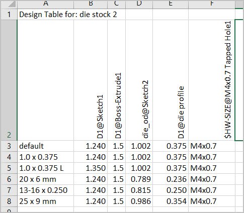
In this part I’m driving configurations by a design table. When drop a part into the drawing & specify the desired configuration within the drawing using Reference Configuration dropdown, the drawing itself is correct. But the configuration name in the title box is referring to something else - the first config in list? Anyway is there some other PRP I should be referencing in title box or maybe a alternate better way to note the corresponding configuration name somewhere on the drawing?
It works OK for me, so can you share a dummy file set (or share your screen) to check.
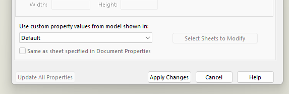
In the meantime, check the sheet properties, and make sure it is referring to the correct view.
How many views do you have on the sheet? The first view inserted typically gets the “default” assignment that gupta9665 shows in the sheet properties. But deleting views and inserting new ones might move that assignment around. So if you have more than one view, be sure to check that each view is set to the configuration you want for that sheet. Or as gupta9665 shows, change it from “default” to the view you want to connect it to.
Last, also try “Control Q” to force rebuild the drawing…maybe its just not updating fully.
Thanks for help so far. The format comment made me notice this was an older SW file & drawing sheet was referencing an old template which may have been affecting things. So I deleted that drawing altogether & made a new one with my current template.
In the new drawing (attached) I confirmed all views reference the correct configuration for that sheet. The dimensions are refreshing & behaving fine. But same issue - the configuration in title box seems stuck to whatever the first drawing sheet happens to reference. I also should have mentioned after making the first drawing sheet, I copy/pasted to N others corresponding to N configs in design table. The intent being drawings all look the same but have their own unique dimensions. Example files attached.
die stock 2.SLDPRT (313 KB)
Sht 20x7: The configuration of View17 is “20 x 6 mm” Not “20 x 7 mm”
Sht 20x7: The projected views are not set link to parent. Sht 20x6 they were setup ‘correctly’.
Sht 20x6: Open Sheet Properties and uncheck “Same as sheet specified in Document Properties”
Thank you! I thought I caught all the configuration selections on drawing sheet but obviously not.
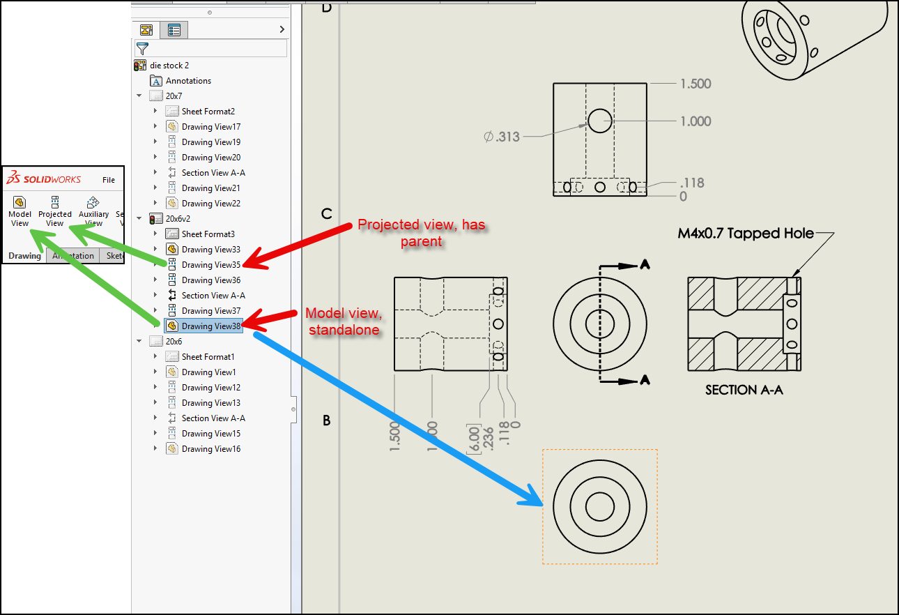
One more confusing thing. The lower drawing view in this screen grab was selected from the right hand views panel & slid into place (after refreshing). Its basically a second instance of the front view, the one above it. Why is it when I look at its available configurations it does not show me ‘link to parent’ like the others?
SNAG-14-03-2025 2.47.22 PM.jpg
die stock 2.SLDDRW (494 KB)
The bottom view is not projected from another view, its just an inserted Model view. Looks like its just a duplicate Front view, only Projected view have the link to parent option. Section and Detail views always link to parent.
Aha! Thank you so much! Its even giving me visual feedback as you indicate, I’ve just been ignoring it.