Just saw a post in the swamp relating to how centerlines appear in SW 2025 Drawings.
The issue is caused by a change that the SW code gurus made to layer behavior.
My question is, to me layers are a leftover from 2D drafting that made it possible to isolate objects in 2D design for clarity. In SW do layers really serve any purpose in the 3D world?
Our solution to centerline issue was to eliminate layers in our drawing templates as we felt they no longer really are relevant to the way we work. Is there any fault to this approach?
I use them, but since I don’t have an AutoCAD background it’s likely not for the reasons most people think. I only have about three though. One is for “Phantom,” which as you might suspect is for sketch lines to display as the Phantom line type.
Another is named “Hidden,” and is for things like hiding sketch lines that I had to add because the software wouldn’t let me reference the desired model geometry with a dimension.
Never used layers until my current job. Here everything, on the drawing, goes on one of 11 layers. The one layer that is useful is ‘Laser Blank‘. When the plant opens a drawing they know what to feed thru the laser.
Export SolidWorks to DWG for some downstream users.
Export for factory CNC process.
Old standards indicated that certain entities be in color. Debatable maybe, but when the factory is getting both drawings from AutoCAD and SolidWorks from different departments, they want to look the same.
A few versions back, SolidWorks did add options to put different annaotations and objects on set layers. So we mostly never have to think about it anymore.
Only use we have here for layers is weldment layer to display welds without having them modeled. The rest is handled by the program. No need for layers to control hidden lines or phantom lines, the program has settings to adress these.
I have a layer called ‘HIDE’ if I want to hide some dims… also a defpoints hidden layer in case I’m sentimental…
Other layers I’ve set up are mainly colors with some set up with line fonts, red, purple, green, blue, etc, in case I want to highlight some dimensions, notes, etc. or sketch entities like drawing view borders or some blocks
When I started there were no layers. There is the tool to hide show annotations to hide or show things that you did not want to show on the drawing. So you could use dimensions to create a note and then hide them. Then a few years later layers on drawings showed up along with all kinds of problems.
When working in a 2d environment they are important tools to be able to turn off lines and dimensions when you need to use the stretch a model for design changes. One could never trust the scale of such drawings so when something close to what you were going to make for another version of the part one needed to start over.
The little programing that I did required dxf, and to do that I would make a drawing scaled 1:1 to convert for that. It was before creating a dxf from the part was available. That tool allows you to map layers if needed.
If a dimension needs color there are ways to do that without layers. Just as easy as clicking on the item and picking the paint brush
We use the dxf export layer mapping option when possible, but it has some gaps in what it can do. We have factory automation and must add some 2d elements on top of the model drawing view since the current dxf mapping doesn’t support it. Examples are barcode stamps, special forming tool punches, etc.
We do our drawings in color. As you showed, you could just color entities with the line format tools. The auto assign to layers they added makes for less work though I think.
Likely forgot…with our move to Windchill and a new product configurator over the last 5-6 years, little has changed on the legacy product side. You may not have dealt with the setup of configurable parts and drawings for factory automation and there are just a few part cases that require the special layers. As for regular drawings, the templates have the auto layer assigment and you really don’t have to think about it, it just puts the entities on layers for you.
Personally, I have never used layers in 2D drawings, as most of the need to hide or shown specific lines can be managed from the view command. I remember in the old days of Pro/E, you had a lot more control of what to display in a drawing than Solidworks, but some of that had to be done via a config file. After reading some of the posts here, I can see that there are some uses where layers could be useful.
The display of centerlines in Solidworks continues to be pants though! It is is very difficult to manage their size effectively, the gap setting between centerlines and extension lines seems to do nothing, and you always have to end up with some compromise. I think the way centerlines work is trying to be too clever for its own good!
Never used layers myself, mapping while exporting handles possible needs. I know one case where company used (maybe still using) layers to create multilanguage drawings…one language per layer → exports
This reminds me of another reason we created layers. When we started on SolidWorks in 98, there wasn’t a centermark or centerline annotation type, not sure which version added them. We used to draw sketch lines to manually create centermarks and centerlines. The layers allowed us to format them easily to set color, linetype, and lineweight.
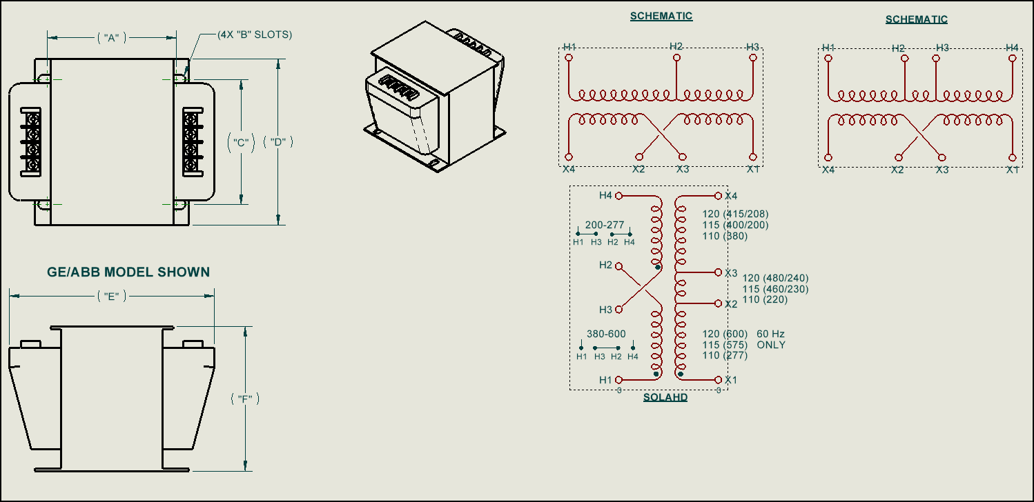
We also occasionally draw 2d stuff to compliment the 3d models view. Schematics views for some electrical components for example:
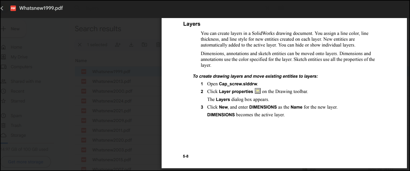
The statement above that “new entities are automatically added to the active layer is the root of the problem in SW 2025. Prior to SW2025 that didn’t actually happen, new entities went to layer they were assigned to in custom properties regardless of what the active layer was. Now they fixed it so new entities go on the active layer so they take on the properties of that layer meaning your centerlines won’t look like centerlines.
So what is the layer setting for inside properties if it goes on the active layer?
why they suddey fix something like that when there are many other issues with drafting, especially with performance and view generation consistency with envelops, alternative views, hide bodies that have all sorts of strange bugs…