I do a lot of designs that have circuit boards in them. We use a lot of connectors that we import for things like USB, RJ45, HDMI. These connectors tend to be made using sheet metal features. Usually, when I import the model provided by the connector manufacturer, I end up with surface import errors. My latest attempted import I tried the STEP, Parasolid, and IGES versions of the same part. When doing the import diagnostics, the parasolid version had only one surface error, but if you tried to repair that, it ended up with another 150ish surface errors in other parts of the model. I had similar results with the other two file types. I tried importing with 3D interconnect on and off.
Have any of you encountered this? Any suggestions?
I have gone through and deleted known trouble surfaces on some models, but that is a lot of work for a part that we are just buying and putting on a board.
I found this on the amphenol website. It imported for me (2024 sp5) without issues.
I frequently struggle trying to find cad models of connectors, but it continues to improve every year. I’ve had better luck trying to go to the source for cad models. Sometimes those included with the electrical package aren’t ideal.
Not specifically with sheet metal features, but with models that were made from a different CAD software.
This is generally my order of operations:
First thing that I do (if I don’t need the history tree of the file), is run it through a “Parasolid wash”:
1a)Save the part out as a parasolid, then reopen it and overwrite the original file. This will also get rid of any legacy template issues if there are any.
Then, if I still run into geometry errors then I will attempt an import diagnostics. If that doesn’t IMMEDIATELY fix it, then I abandon it completely, because it tends to get worse. A lot worse.
I will then run a stringent check diagnostics to find any surfacing problems. If they are simple, I might fix them myself (delete bad surfaces and replace with 4 sided surfaces or create an extrude cut to cut away the problem area, parasolid wash again, then replace the area).
If that still doesn’t work, or is too complicated, then I will consider modeling the part myself.
We have a single seat of Transmagic here that I will then attempt to wash the part through. Either my post washed part, or the original file, whichever one turns out better.
If none of those things work, then I will either deal with the errors, or if I can’t (because downstream things are breaking), then I will contact the place that gave me the file and request a different translation (if I got STEP, then ask for Parasolid, or whatever)
It isn’t a very clean method…but it works most of the time.
It’s a Creo STEP file, of rather old vintage (Creo 3.0, if I’m not mistaken). Unfortunately, Creo-generated neutral files, and especially those from older versions, often don’t harmonize 100% with other systems, This may have something to do with the Creo underlying modeling paradigm allowing ZTG.
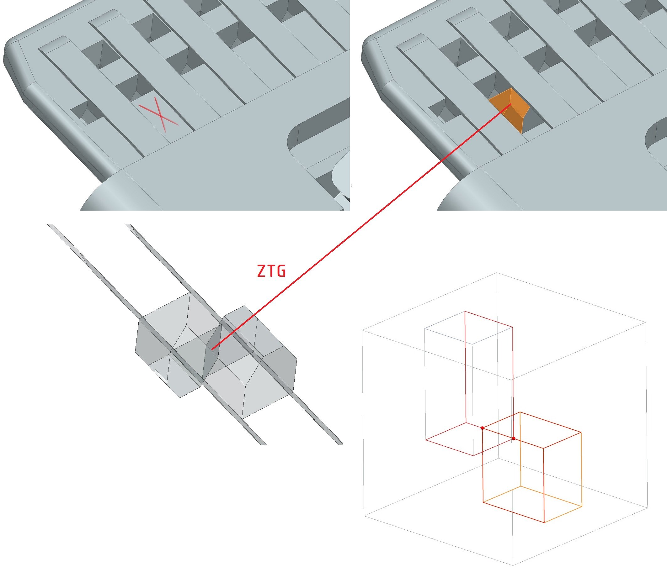
This model has myriad “face intersection inconsistencies”: (edit: ZTG is indeed the issue here, see next post below)
That said, if the body integrity is ok (as it seems to be in this case), such models will usually be generally workable with modeling commands. The wobblers usually start getting thrown if you try to pull individual faces as surface bodies. YMMV.
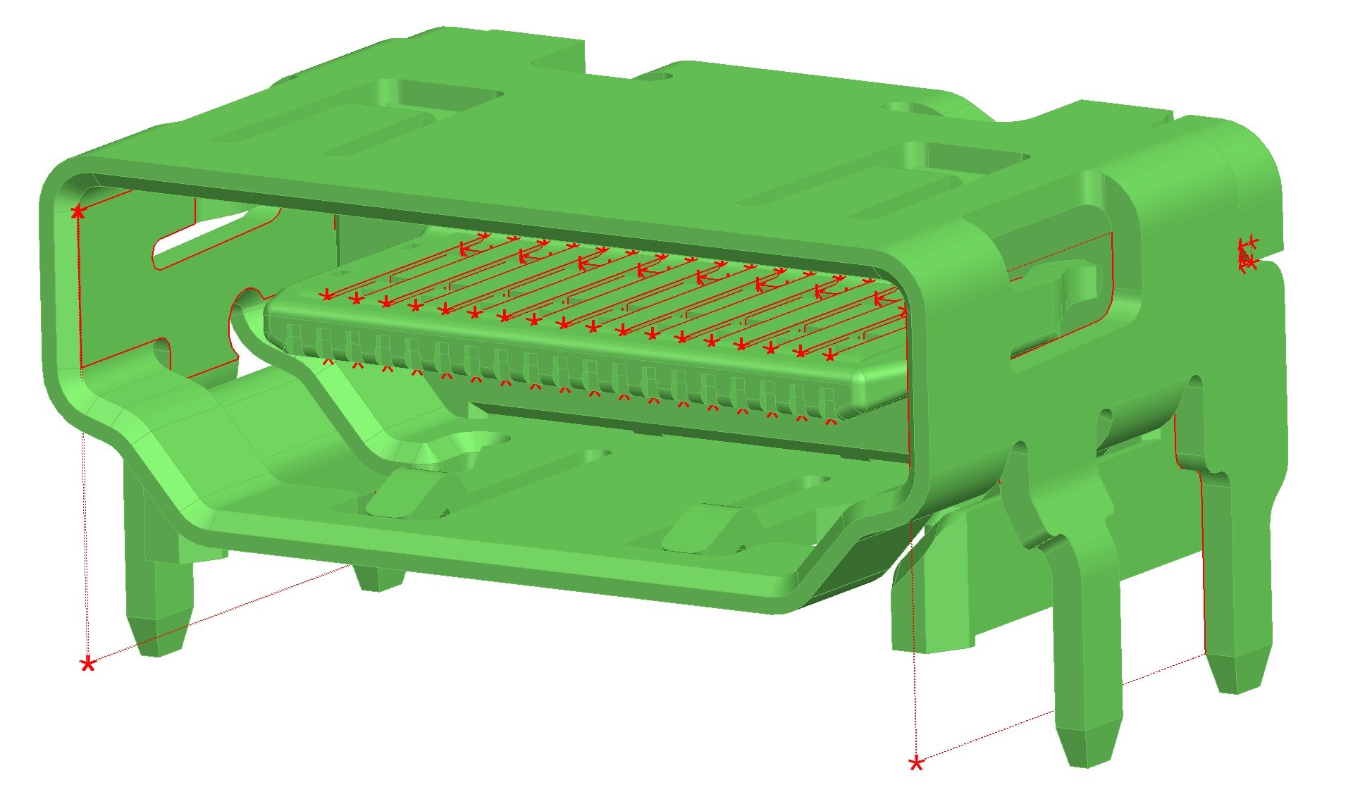
There is definitely some ZTG in the plug area. The hollows cut in from above and below share common edges, and though the ZTG can be imported, a diagnosis in SW or NX will declare these surface intersections as uncool. Schematic representation bottom right, you can import ZTG into SW and NX but you can’t create it.
Since these parts are headed towards being library parts, we don’t want things that have errors. The errors in my experience end up making things just a bit slower and over the life of a project, a bit slower can really add up.
I ended up in a meeting that I didn’t need to give complete focus to and worked on this model some.
For things like the problem in the contact area, I created an extrusion and filled in that whole area. I then exported and imported. I deleted some of the surfaces that were causing the problems or filled in over them (I don’t remember which I settled on, I know I tried both) then exported and imported.
I know where to look for the problems. It’s where sheet metal surfaces are touching typically. We end up with one surface trying to be shared where SolidWorks needs two.
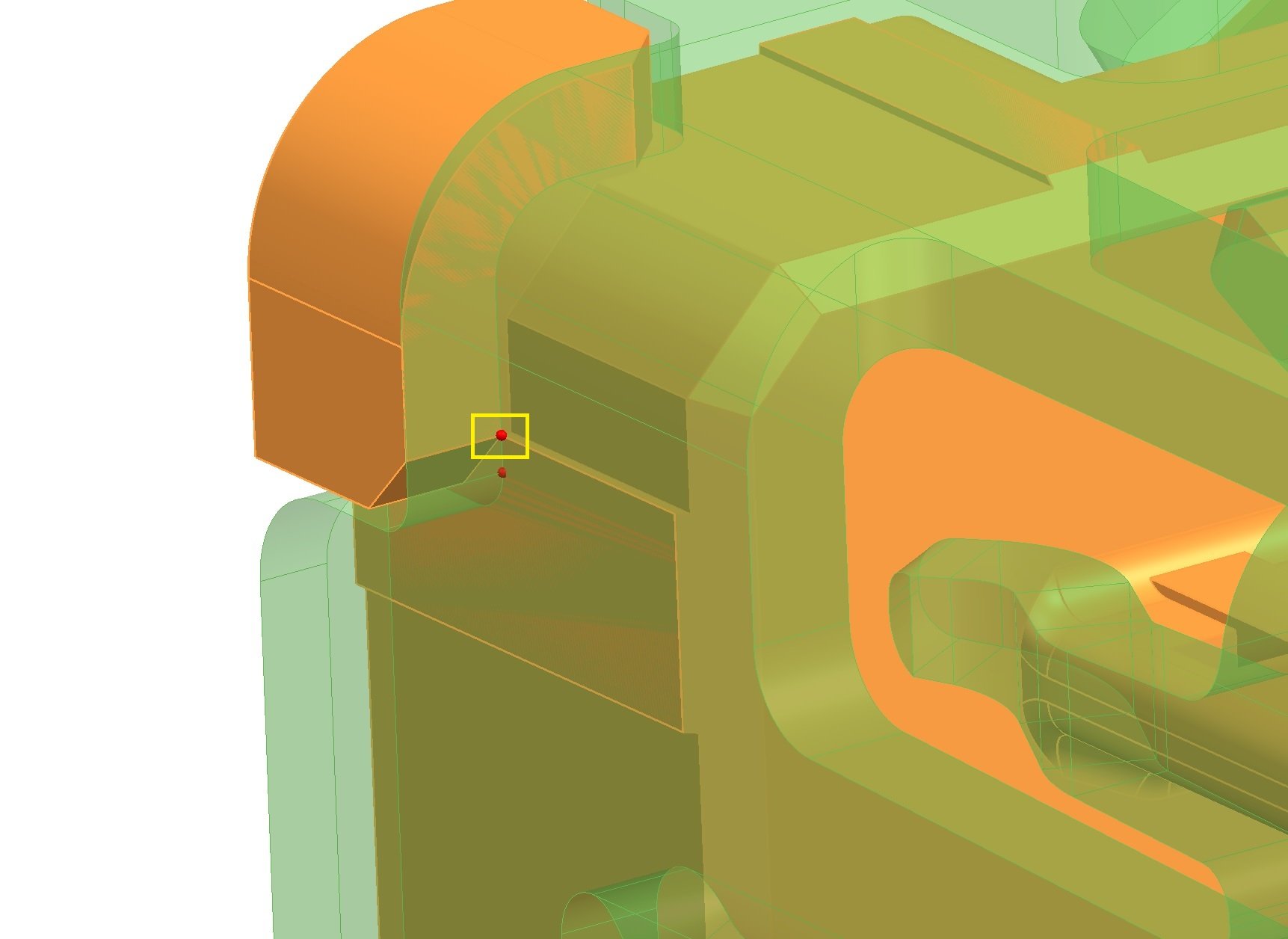
Sheet metal edges can do it, and “illegal” fusing of multi-bodies happens a lot too with catalog parts. Fusing the shell and the insert created a ZTG vertex. Creo allowed it, but trying to Join these bodies in SW will cause an error due to the vertex.
So another way to fix such a model might be to separate it into its original constituents.
As far as I’ve heard, there’s currently no even semi-automated way to get rid of ZTG… maybe this will be new ground for AI.