Ah yes. Installed to do some testing on a new “feature” (i.e. an option touted as a “feature”):
The “Z” & “Y” Up setting toggle and low and behold… is this DS amateurism shining through or am i missing something?
It seems to have NOT been a simple toggle between Yup or Zup because the damn thing appears to rotate AROUND THE “Z” axis at the same time. WTF?
If i’m missing something please let me know but i sure as hell don’t think i’m the one that’s missing something here… Last time i checked, the only difference between the two methods is a simple 90 degree rotation AROUND the X axis - AND NO OTHERS.
To many DEI hires and “cloud” fluff over at DS me thinks. What a clown show.
Screenshot 2024-11-19 13.31.58.png
If you set your template to Z-up, your new parts will be modeled with the z up as you want it and the default "Front, Top, etc views will match.
Switching this on an older part just rotates the view…the part will not be reoriented nor the global Csys rotated. Doing so would’ve likely broken existing assemblies and drawings. I had a part that I didn’t like how it was oriented and went through the painstaking process of refining the planes that sketches were on and got it set. The drawings views were all turned as the “Front” view was now the “top”, the assembly had mate errors due to mates to the part’s planes that were now rotated 90°.
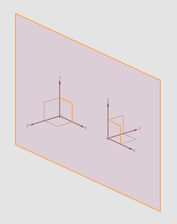
That’s the thing.. these are completely new parts based on cleanly created v2025 templates, and, as indicated in the screenshots, they clearly show a rotation around a DIFFERENT axis AS WELL AS the ‘x’ axis. Which as far as i can tell is NOT what should happen. It should be as simple as what’s in the last screen shot.
Thanks for the replies, but so far it seems i’m not missing anything and its DS that have fluffed up a simple x-axis 90 degree rotation. I’ve translated for days from SW to other applications that use Zup and to get the models “right” in those is a simple X axis 90 degree rotation when going back and forth. Yes the models will still be “Zup” now but the coordinate system should not be rotated around the Z axis when changing to Zup (as it is shown in my screenshot with cleanly created base v2025 stock part templates).
Hi SPerman, Sketch editing in a file of each orientation. Seems the main indicating coordinate system remains the same. Which is, IMO, rotated around the Z axis wrong by 90 degrees as “X” is pointing “out” of the screen when it should be in the orientation that the “Y” axis is.
If i didn’t absolutely despise using the SWOMP i’d “report” it. But i can’t figure out how to and CBF trying to figure out what should be a clean, basic process just to report something that wont get fixed and cause me an aneurism to report.
I think the point is being missed. the Zup direction is fine. that HAS changed as per the “enhancement”. The problem is the extra rotation around that new world coordinate system’s Z direction ON TOP OF the X axis rotation to achieve Zup.
They have rotated the World Coordinate system around two axis instead of JUST the “X” axis to achieve Zup. I am trying to determine if there is a reason for this or its a mistake (my bet thus far is an error as no other system includes 2 90 degree rotations to convert from Yup to Zup or back again).
When i get a chance i’m going to check fi the exported models actaully adhere to this change in “X direction” once imported into other systems.
EDIT: Test confirms my suspicions (that its a fu*k up). i.e. there are two rotations when there should only be a single rotation about the X axis.
You should name your planes and set up your views however you like and move on. Which axis goes up or North or whatever is arbitrary and has no real meaning. I can imagine that people in the automotive space use the out of the box orientation for Zup that DS is using. I would be more inclined to argue that what is labeled right plane is really on the left when looking at the plane from the positive 3rd axis side, but I have the planes named in a way that makes sense to me. DS can be criticized for lots of things but this isn’t one of them.
Really the only reason why it matters to most people (from my experience) is for CNC programming. There is a standard for most machines and CNC programs. Solidworks does not follow that standard, and any file brought into a CNC program has to be rotated for said program. Either before translation or after.
You are the one talking about something unrelated to the issue raised. Even when i tried to get the focus on A)what i was actually talking about, and B) what is ACTULALY wrong.
If that were the case no one would have named the axis XYZ to differentiate them. Also, when translating between other systems and softare, it seroiusly does matter. Wasted time is a huge “matter” and translating CORRECTLY creates lots of wasted time, which again, matters.
DS didn’t create SW, they bought it and assumed this decision of Yup that was made long before they came along so their “automotive space” has nothing to do with it and is just a made up irrelevant strawman.
I thought you said the planes mean nothing, now you’re not only naming them, but naming them so they “make sense”?
Completely irrelevant point. I have pointed out they have added a 2nd rotation when a single one is all thats required. Try to stay on point next time or at least address the point before arguing about teh price of eggs in china.
It’s maybe not arbitrary, but its certainly conditional based on your product and industry and processes. And its different depending on who is looking at it and what they do. The CNC guys idea of “Z” is going to be different than the engineer’s idea of “Z”, versus maybe even the customer.
I’ve asked the CNC guy and the BIM guys we export models to about it and they just say “We rotate it to however we need it, what’s the problem?” 25 years of SolidWorks and it’s hardly ever come up. For one BIM export, I did insert a user coordinate system to select in the “Save as export” so it would import into the Revit assembly in the correct location and orientation. That was a unique case though although I could see applying a default user Csys for that purpose in your templates if its a common need.
Which way is up on north pole?
Which way is up on south pole?
Which way should the model use as up? When installed? Machining? Packaging? Shipping? On north pole? On space station? On moon? Mars?
Which way is up for a bolt? Nut? Washer? Ball bearing?
Which way is up on a lathe? Vertical mill? Horizontal mill? 5 axis? 3D Print? Resin print?
How many models do we need for each different Z?
I agree that what you call up or what you names you give the planes doesn’t necessarily matter, but consistency leads to efficiency. If I can build all of my main sub assemblies in the same orientation as the main assembly, it saves time when bringing it all together. The less time I have to spend flipping and moving things in solidworks to make that happen, the more efficient I am. Cumulatively, I’ve spent many hours having to flip the sketch on the front plane so that z is up, not down.
I agree with this. I always try and model parts with some regard to how it would look if I were standing in front of the product. That way, when you drag them in to build assemblies, its less manipulation as they are already oriented. I don’t pay much attention to XYZ, just what SolidWorks calls the “Front” as a default. Outside of that, exporting is only time this seems to be a problem.
I’m in agreement with the “it doesn’t matter” crowd on this. Yes, making parts in the same orientation to make assemblies easier is a good thing, and probably a good practice, but if I import a part or bring in a old part that has a different orientation I’m just going to use mates to get it where I want it in an assembly and not remodel it. You could already could change what view was front/top/right to go with the view buttons, so how you model it is not very important in my opinion.
Also, as far as CNC programming goes, all the software major packages can handle any orientation of the model because you can define your your programing axis in the CNC program. You want to machine on the right side, X-Up and y-right then you set that, you want y-left you change the machining plane accordingly, it’s all done on the fly, no need to rotate your model.