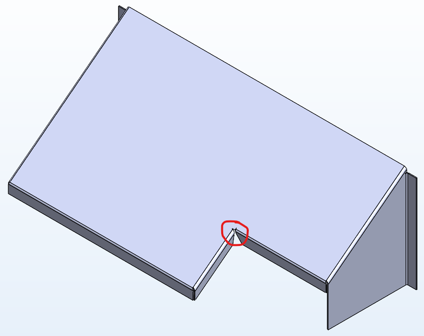
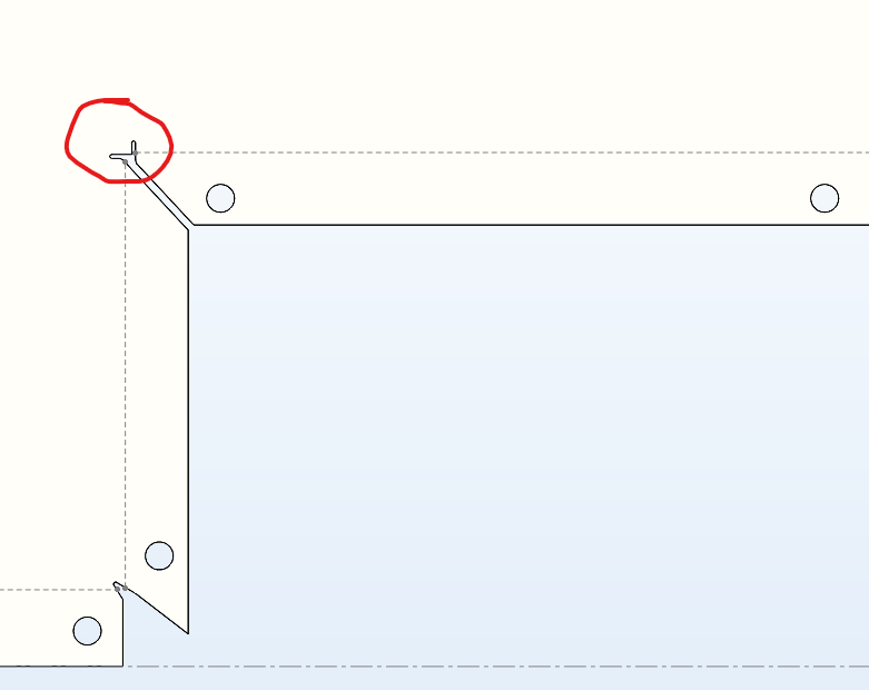
I figure since we’re kind of talking about formed sheetmetal parts, this might be a reasonable opportunity to ask this question, but at this point it’s purely for my curiosity—We will be farming this part out of house, we need exactly (1) piece, and the drawing has notes that say the joints may be placed per vendor discretion and the item may be made from more than one piece of steel.
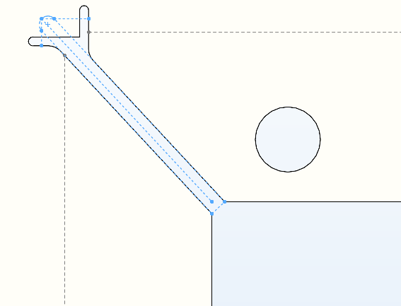
But golly, I would really like to know how I am supposed to get this joint relief (circled in red below) right. I can see it in my mind’s eye, but I can’t get SolidWorks to see it. I am also attaching a part file so you can see what I did.
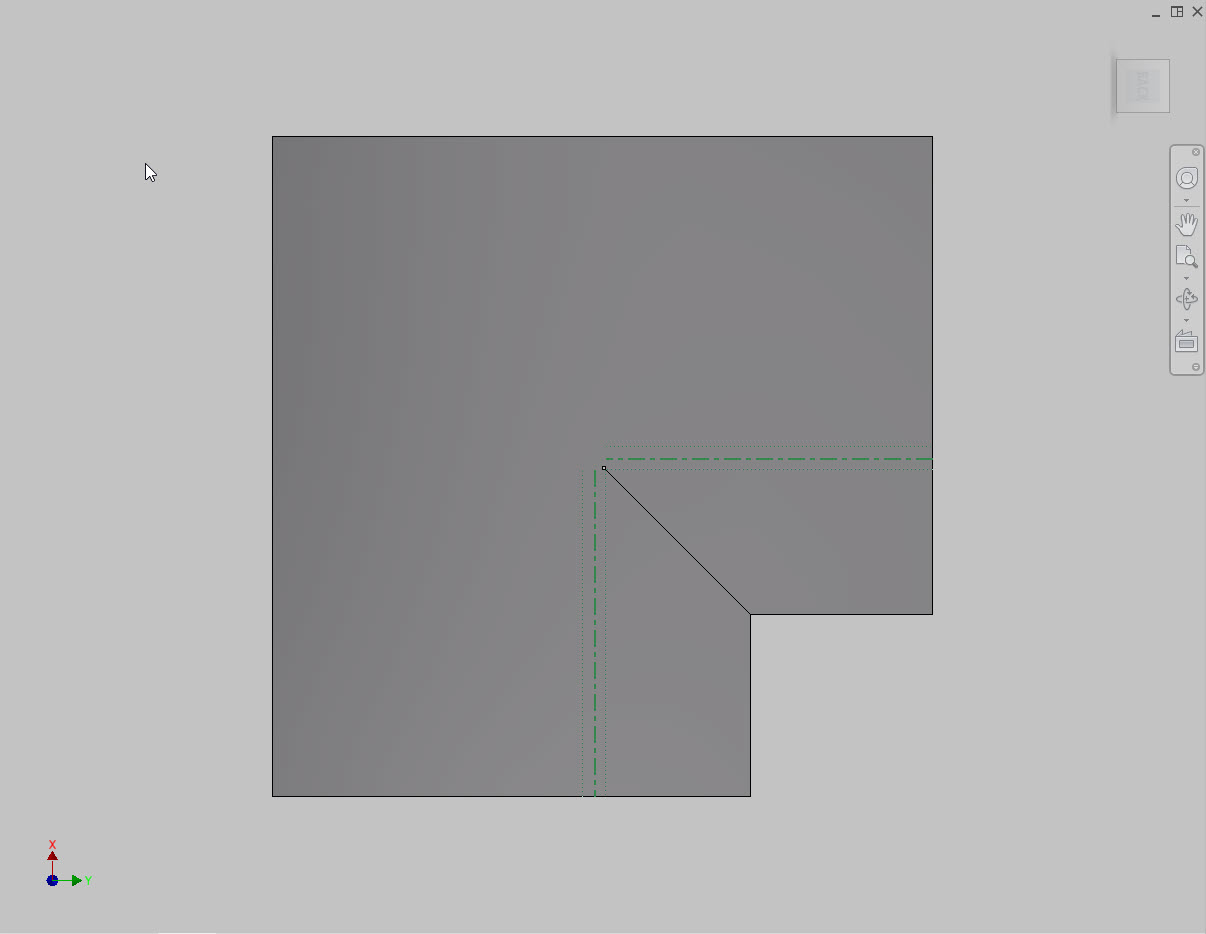
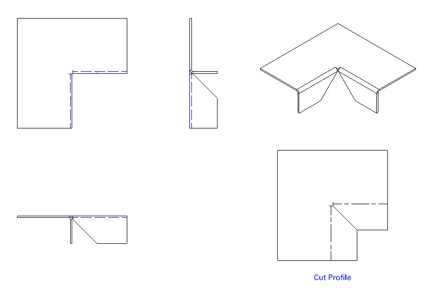
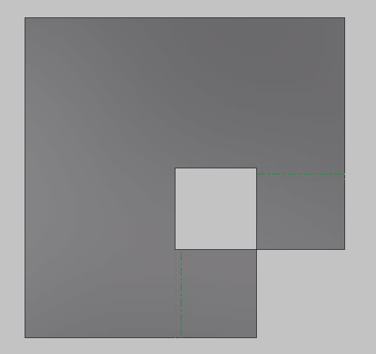
That’s an impossible corner with those walls unless when flattened the edges have a clearance. Maybe I’m seeing it wrong. What does this look like flattened?
SWX gives you a lot of control over the corner relief, but if you have to you can add a relief cut in the flattened state.
You know, that’s not the worst idea I’ve ever heard.
But to be fair, in this office we have also suggested machining an entire 40,000 lb machine out of a monolithic block of steel on site at the customer instead of shipping a completed machine…
When that was shot down, someone else suggest child labor
I’m not sure I understand (but it’s not your job to change that!)
It sounds like you’re saying the width of the gap determines how far a flange will be bent, but it seems like you could bend either flange to 27.3° or 48.9° or 90° as long as there is clearance for tooling?
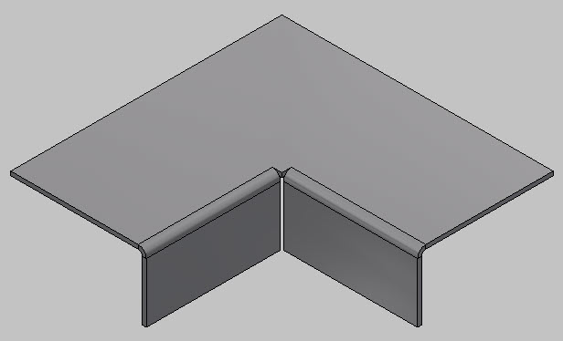
@Frederick_Law Is correct in that to bend the first bend of that corner, the die is going to want to bend part of the other flange. Or if the die does not go all the way along the bend & the flange will want to stay flat where the die does not support it & you could end up with some distortion.
That being said, if it 12GA material or less it may not make much difference, and the piece could manually manipulated into the proper shape after the brake has its say on the part.
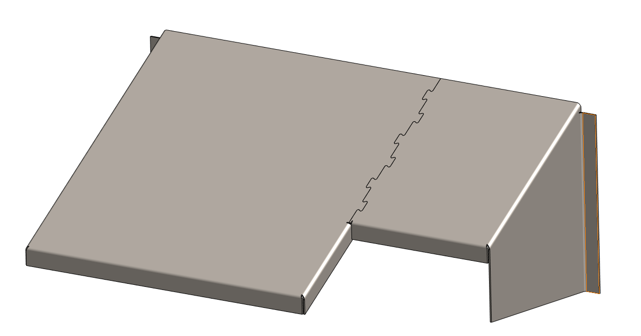
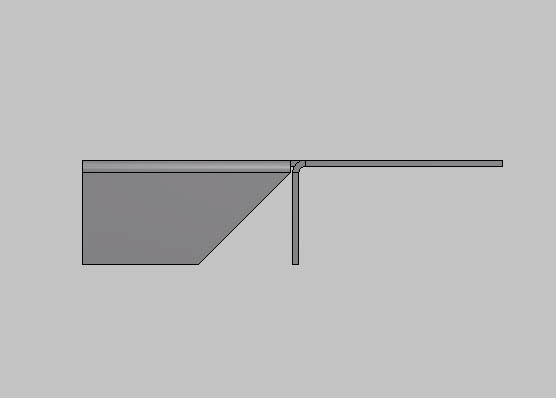
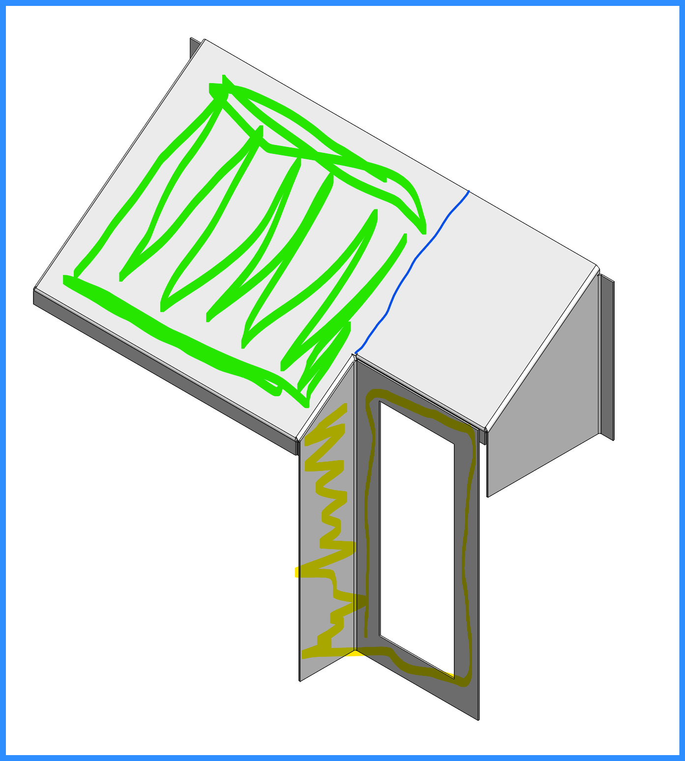
Since you already have the part in 2 pieces why don’t you split it where mihkov depicts and add your second piece to the main base flange such as shown here? Combine the green and yellow and split along the blue line.