So I have a sheet metal part I need to make that I am not sure how to do. We take a flat piece of material and bend it 10 degrees in 0.25" from the edges, its kind of similar to a outlet wall plate, just larger and more rounded on the corners
https://drive.google.com/file/d/1AYoPPFue3ku6rk_nCqW-q8C-KCg7R4nq/view?usp=sharing
My problem is when I make it as a sheet metal part I can’t do edge flanges and get the rounds in the corners, when I try to make it a sheet metal part from a solid it again doesn’t like the rounds in the corners. Does anyone know of a good why to model it?
Material is 18Ga SS (0.048)
Size is 6.375 x 3.875, 0.25 Radii in the corners
bend is 10 degrees down 0.25 in from the edges
Probably the forming tool feature will be successful, and closest to real manufacturing process as well.
You can use a Swept Flange, this may depend on which version you’re in though. This example is in 2022.
First did a Base flange.
image.png
Add sketch to one end for flange:
image.png
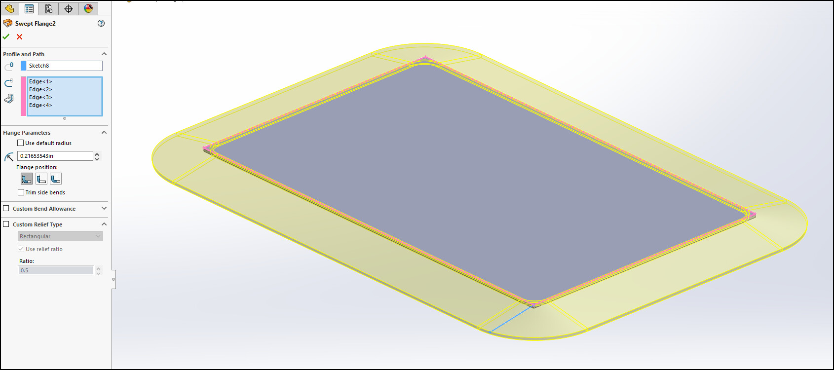
Select profile and edges for swept flange:
image.png
Finished part:
image.png
Thanks Jason, that is what I wanted
That’s not technically a sheetmetal part, as far as Solidworks is concerned…
It’s not manufactured via sheetmetal forming processes. You can’t make that in a sheetmetal brake.
It is a stamping. made with a stamping die.
This is true, it would take some trial and error with the bend allowances to get an accurate flat. We have some parts that have “hard tooling fixtures” that bend parts by stamping, so normal bend allowances don’t work. We even have to adjust and override bend allowances per bend.
We do it in a press break, the bends are there so the gasket under it seals better, so the angle and corners are not that critical. The corners deform a bit different when you hit the adjacent sides. I needed it as a sheet metal part to get the blank size.