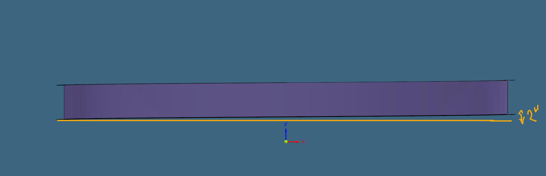
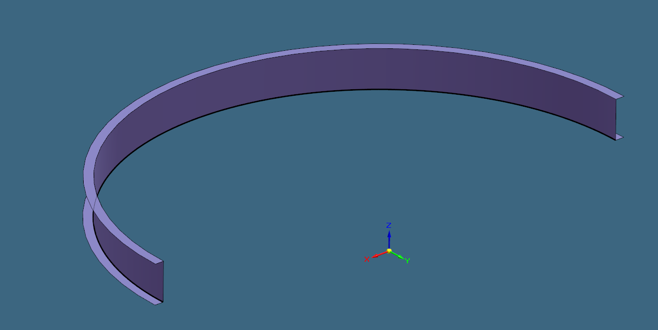
Is SE able to create a 180deg helical curve with flanges that can be then flatten. The incline from one end to the other is about 2inches / 50mm. Have tried to create a surface, then thicken and the use “thin part to sheet metal”. But it’s not working!
Appreciate any ideas on how to approach this or if this is even possible in SE!
Yes, the previous was about how to get the flanges on the curve with no incline. So, the curve was flat on the ground. But now I am looking to have a curve with an incline from one end to the other (helical)!
No I am just evaluating the software SE and comparing it to SW what is possible. In SW this is also not doable the flanges need to be separate body to flatten it but thought SE can! And hope some expert knows the answer.
So, this can be done in Solid Edge, but you cannot use the typical Sheet Metal Flat Pattern command. I actually did this in SE 2023 in Part using a helical curve and a cross section representing the sheet metal shape to sweep along it, then used the Sweep command to create the solid. Then I went to the Tools ribbon, selected Flatten which will automatically invoke the Blank Body command. Went through that to generate a flat pattern.
I tried the same in SE 2022, but the Blank Body failed to flatten it. SE 2023 was successful.
Just tested that and it works in SE 2023 community edition. It’s not native sheet metal, but once flatten it gives pretty accurate result. I know this can be done with surfaces both in SW and SE, but this is on another level with solid bodies. Thanks
I’m certainly no expert, but after being on Solid Edge for ~8 years combined, the company had been using it for over a couple of decades where ~45% of our part files were .psm, before switching to Solidworks I can say with good confidence that Solidworks is still about 5 - 10 years behind Solid Edge in Sheet Metal functionality.
Think of the SE Sheet Metal environment as a tool for sheet metal you will run through a punch press and then break or fold. Roll forming is valid too if linear. Anything formed or non-linear is better done in the Part environment as those tools will probably be needed and you can Switch to Sheet Metal if you need something like the Dimple command that bnemec mentioned. Likewise, if working with bent sheet metal in the Sheet Metal environment, you can Switch to Part to do those “punch” features you need, but know they will not flatten (nor do they really need to) with the regular Flat Pattern tool.
The Blank Body command is specifically designed for formed sheet metal and will do it’s best to account for stretching due to drawing of the metal. I’ve heard it called the “Flatten Anything” tool.
Is there any need to use the .psm sheet metal template? What are the benefits of saving in this format. As I could just have .prt and the switch between when needed!
What’s a good workflow when using both synchronous and ordered. First sync → ordered → sync or opposite way?
And is there a way in SE 2023 to make the icons bigger except windows scaling?
I don’t know why they still keep with the .psm file type. The file can be switched back and forth. From writing our auto DXF add-in I learned that there’s a meta-data tag in the file to identify it at sheet metal or not. Cannot go by the file type any more.
Oh, boy! Here we go. I’m not allowed to speak on this topic here.
I only have 2019, and it states that the system scaling is only option. Note that SE implemented system scaling much differently (and possibly better) than Solidworks. I found that new users benefited from keeping the tool-tip videos on. for a while. Typically, large icon is more of a beginner mode, then once memorization and muscle memory kicks in users want smaller icons for more workspace.
image.png
FYI,
We have recently made the transition from SW to SE. Most of our stuff is migrated by now. And I will attest it was well worth the pain of migrating. We do a lot formed sheet metal design which is where sync really shines. So we use sync very heavily, which makes migration fairly easy. If we wouldn’t use Sync much I don’t think it would have been worth it b/c SE Ordered kinda sucks compared to SW.
SE Draft also outdoes SW by a long shot, esp. their BOMs.
I checked and I noticed it adds these Custom Properties when you create a Sheet Metal feature in a Part file. Do you use one of those?
image.png
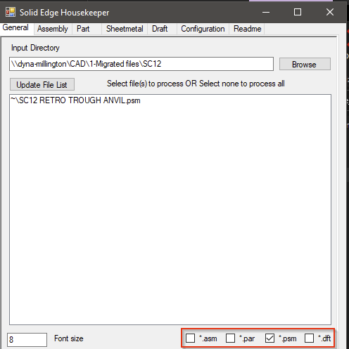
The nice thing about using a different extension though is for filtering like this:
You can filter on file extension type, but if I’m not mistaken your results will not be accurate. There can be sheet metal parts in a .par file and regular bodies/parts in a .psm file. The latter not as common as the former. When editing a solid part file the user can convert to sheet metal and have a sheet metal part in a .par file. So filtering by .psm may very well miss sheet metal models. Maybe this doesn’t matter for housekeeper usage, I don’t know. I can tell you it sucks when trying to replace one model for another in a bunch of assemblies, IIRC Design Manager would not let me replace a .par with a .psm.
I agree SE feels more stable with draft then SW and also when it comes to larger assemblies. At the end I decided to go with NX! It can handle even better larger assemblies and feels snappier.