Seems it has always been an issue with selecting the center of a hole of a rolled sheet metal component that has been flattened. Are there any successful and repeatable methods to select a hole center in such a configuration of a part?
How did you create the rolled sheet metal part and holes?
I agree with jcapriotti on this one. If you created a round hole in the part while in the rolled/formed/bent state, you will end up with a distorted hole in the flattened state. If the hole is created while in a flattened state then you will have a distorted hole in the rolled/formed/bent state.
This issue has been around since the inception of sheet metal in SWX 97. The features are put in when the plate is in its rolled condition. Due to customer requirements of how they are located, calculating out their position in a flat pattern configuration does not satisfy the accuracy they need. Considering these parts are 1-1/2 and 2-inch plate with bend radii of 72-ft and larger, the errors over that distance is exaggerated, when placed in flat pattern. I have always hoped that since SWX can locate the center of an ellipse and slots, that the programmers may have come up with a solution by now to deal with the virtual distortion of the feature, be it a hole wizard entity, or a simple cut.
If the holes are put in when in the rolled condition, why are they shown in the flat pattern at all?
The plates will go on our laser table to have the holes put in them, then rolled after that.
I’m guessing the laser takes in the dxf that is created from the the Solidworks Flat-Pattern? What is the purpose of the center mark?
The table will actually take the model being there are multiple angular cuts also, as well as a simple dxf, but there are surface features that are required to be added based on the center of the penetrations in the flat. Hence the need to be able to snap lines, dimensions, etc., to those within the drawing environment to better locate them. Good questions.
Am I hearing that thickness the kerf/cut? angle matters so the torch/laser angle may not always be normal to the plate? Your CNC cut data is not simply 2d? I’m used to 16ga-3/8” where hole geometry is whatever the laser wants and largely irrelevant.
I played around with this a bit and confirmed my suspicions, they don’t bother trying to calculate ellipses or other privative elements, it’s all splines. So there will never be center marks unless they modify how flats are created. Which I personally hope doesn’t happen as they always enable new features by default and we would be in such a mess…
Now I’m more curious, are you using the approximated flat geometry for cut profile or is that what you’re doing in the flat (after the Flat-Pattern feature) with surfaces?
Appreciate the effort you are putting in to try and pin this down. We do use the model and coordinate to do the cutting and processing then overlay multiple dxf patterns to do a lot of the secondary marking operations. No, the head will not always be normal to the plate as it will articulate to form countersink holes, bevels and multi-angle bevel transitions. The plate thickness cited earlier in this thread, are the thinner plates too.
I have used this same approach on single and small pattern count features. I should mention there are hundreds of locations that vary greatly, and this approach would take literally days to accomplish. Would be especially painful for revisions later if and when the design changes. But a good suggestion.
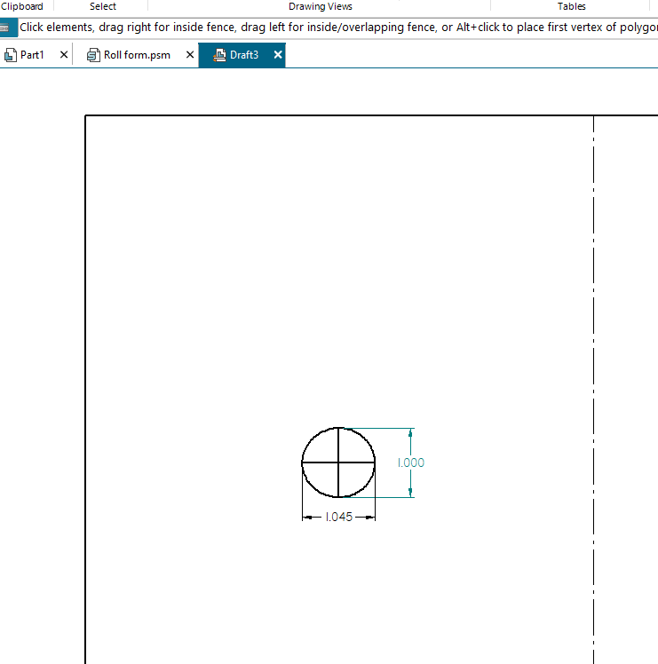
Would sketching in a 3-point circle coincident with the edges of the hole get you close enough? It would be constrained to the hole, and then you could use the sketched circle for things like location dimensions/centerlines/etc.
I’ve been noodling a bit about what might work for that. We do a fair bit of direct edits after the flat pattern feature to clean up non sheet metal features. Delete chamfers, indents, etc that do not prevent the model from flattening but produce lines on the dxf that we do not want. It’s pretty straight forward to do what Josh suggests to get very close approximations. It seems like that’s something that could be done through APIs, allowing a macro. The problem with tangents is they seem to like to flip to the wrong spot; I’ve not learned how to predict their behavior.
I was about to post a question here when it dawned on me that we’re already discussing it in this thread, just asking the question differently but it boils down to the same problem.
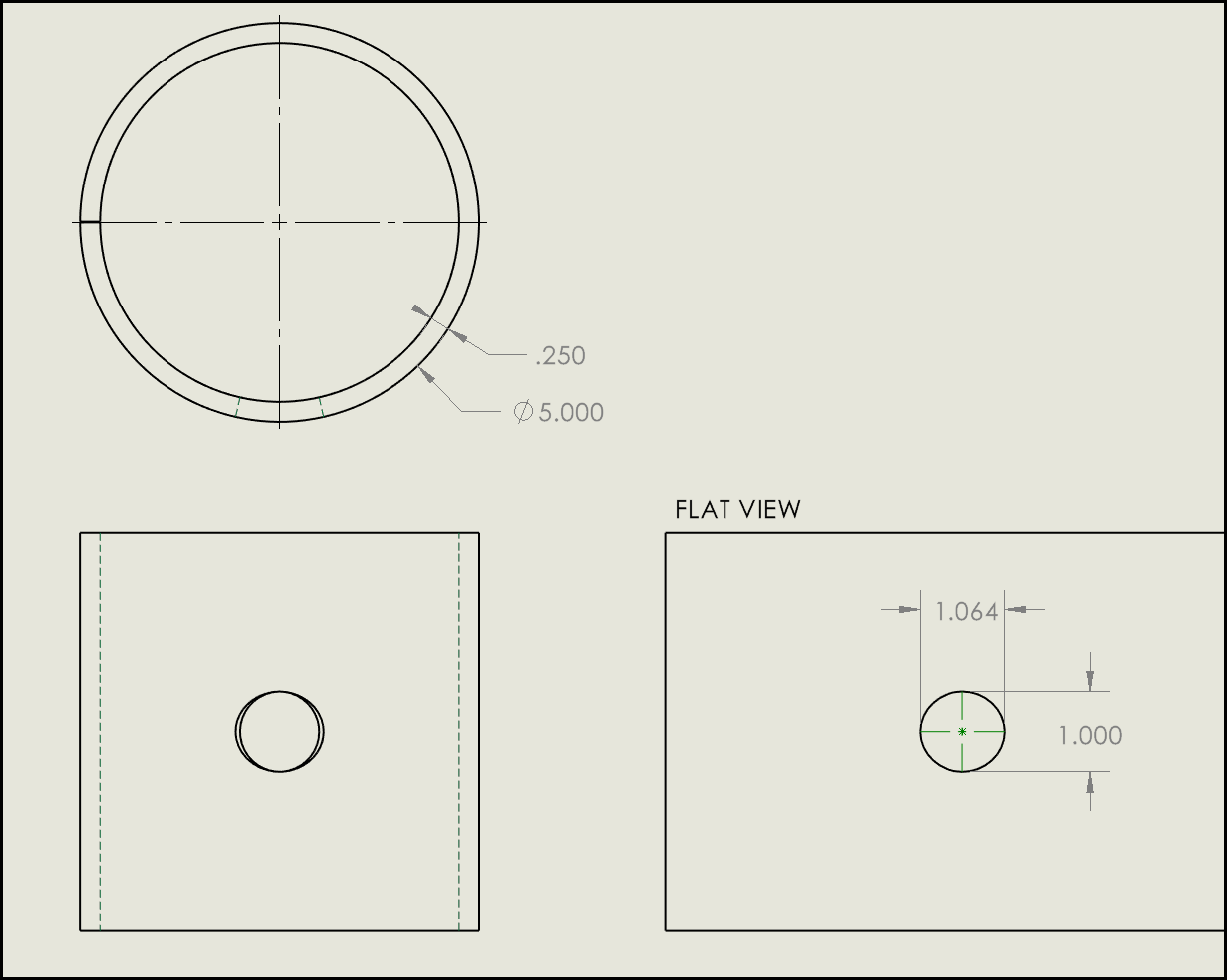
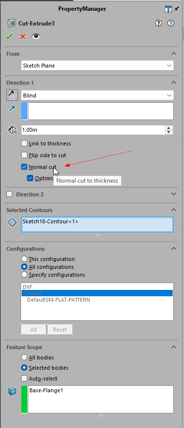
Who uses the “Normal Cut” checkbox in Extruded Cut feature properties >and< dimensions the hole in a drawing? Yesterday I encouraged coworker to use it as it produces a pretty accurate profile in the flat pattern that our laser does well with. Today I reviewed his drawing and noticed the cut profile is a slot. So I enjoyed the humbling when my young co worker explained to me there’s no way to dimension what “Normal Cut” produces in the drawing. I’m guessing we’re doing something wrong as I wouldn’t think they would advertise a modeling feature that produces elements on a drawing that cannot be dimensioned. Keep in mind I’m still trying to forget how to do this in Solid Edge.
I’m not talking about the Normal Cut feature, I’m talking about the Normal Cut check box/option in the Extruded Cut feature property manager.
I tried this in Solid Edge and it comes out pretty much the same. Normal cut is a separate feature instead of a toggle in a regular cut extrude, but seems to do the same thing. In the flat you end up with a slight oval based on k-factor. Can only seem to dimension the spline “length”. I had to draw some reference sketch lines in the drawing to get an ellipse.
See what you think of this macro… It works inside of a sketch in assy or part documents, or in drawing views.
If you are in a part or assembly, start a sketch on a face. If you’re in a drawing, just pick edges. Select one or more closed continuous edges and run the macro. For each edge, SW will:
-Create a polygon with three sides and a circumscribed circle
-Add coincident relations between each of the three vertices to the edge.
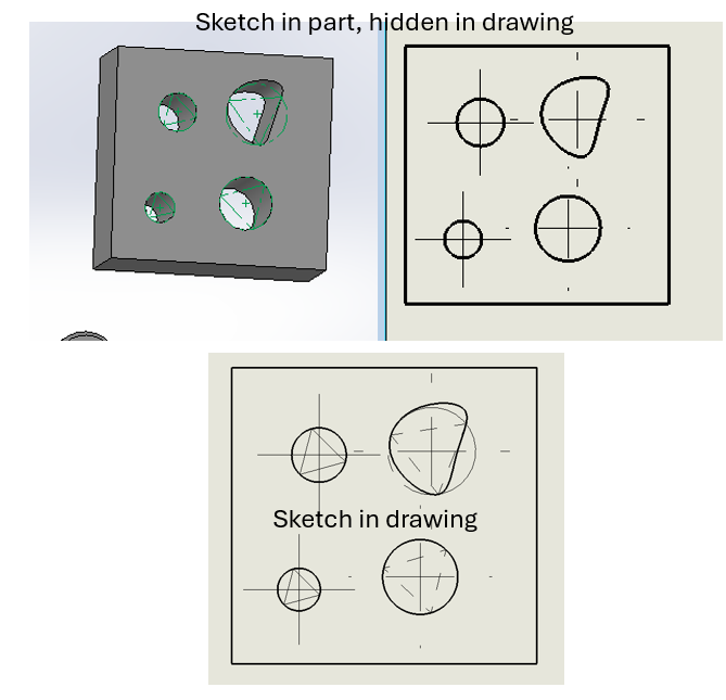
Obviously , the closer your entity is to truly being a circle, the better your approximation is. Also, the triangle is not fixed in rotation, so the center can move around. But again, if your edge is only varying from a true circle by 4.5% or so, the center will be pretty dang close.
If this is done in the drawing environment, it will add a centermark to the circle automatically. Downside is that you can’t directly hide the triangles in the drawing view. The macro could automatically move them to a different layer that could be turned off or set not to print though.
IF this is done in the context of a sketch in the part, you can show the sketch in a drawing view, add a centermark to the circle, and then hide the sketch in the drawing view.
Dim swApp As SldWorks.SldWorks
Sub main()
    Dim swDoc As SldWorks.ModelDoc2
    Dim swSketch As SldWorks.Sketch
    Dim swSels As SldWorks.SelectionMgr
    Dim swSeg As SldWorks.SketchSegment
    Dim swSkArc As SldWorks.SketchArc
    Dim swSkLine As SldWorks.SketchLine
    Dim swCurve As SldWorks.Curve
    Dim vSegs As Variant
    Dim cPts As Collection
    Dim cPtVals As Collection
    Dim swPt As SldWorks.SketchPoint
    Dim swEdge As SldWorks.Edge
    Dim cEdges As Collection
    Dim i As Long
    Dim j As Long
    Dim k As Long

    Set swApp = Application.SldWorks
    Set swDoc = swApp.ActiveDoc
    Set swSketch = swDoc.GetActiveSketch2
    If swSketch Is Nothing Then
        MsgBox "You're not sketching"
        Exit Sub
    End If

    Set swSels = swDoc.SelectionManager
    Set cEdges = New Collection
    For i = 1 To swSels.GetSelectedObjectCount2(-1)
        If swSels.GetSelectedObjectType3(i, -1) = swSelEDGES Then
            Set swEdge = swSels.GetSelectedObject6(i, -1)
            Set swCurve = swEdge.GetCurve
            If Not swCurve.IsLine Then
                cEdges.Add swEdge
            End If
        End If
    Next i

    If cEdges.Count < 1 Then
        MsgBox "You didn't pick any edges."
        Exit Sub
    End If

    swDoc.SketchManager.AddToDB = True
    swApp.SetUserPreferenceToggle swSketchAutomaticRelations, False

    For i = 1 To cEdges.Count
        Set swEdge = cEdges(i)
        Debug.Print "Edge " & i
        vSegs = swDoc.SketchManager.CreatePolygon(0, 0, 0, 0.05, 0.05, 0, 3, False)
        swDoc.ClearSelection2 True
        'Debug.Print UBound(vSegs)
        Set cPts = New Collection 'Need to get 3 sketchline endpoints to add constraints
        Set cPtVals = New Collection
        For j = 0 To UBound(vSegs)
            'vsegs should contain the circle and three lines.  Get the start/end points of one line, then the point of one more line that is not already found.
            Set swSeg = vSegs(j)
            swSeg.ConstructionGeometry = True
            If swSeg.GetType = swSketchLINE Then
                Set swSkLine = swSeg
                If cPts.Count < 1 Then 'This is the first line.  Get both points.
                    cPts.Add swSkLine.GetStartPoint2
                    cPts.Add swSkLine.GetEndPoint2
                ElseIf cPts.Count = 2 Then 'Else should mean we already have two points.
                    If (swSkLine.GetStartPoint2 Is cPts(1)) Or (swSkLine.GetStartPoint2 Is cPts(2)) Then
                        'start point is already found.  This means the end is new.
                        cPts.Add swSkLine.GetEndPoint2
                    Else
                        cPts.Add swSkLine.GetStartPoint2
                    End If
                End If
            ElseIf swSeg.GetType = swSketchARC Then
                Set swSkArc = swSeg
            End If
        Next j
        Debug.Print , "Found " & cPts.Count & " poitns"
        For j = 1 To 3
            swEdge.Select2 False, 1
            cPts(j).Select2 True, 1
            swDoc.SketchAddConstraints "sgCOINCIDENT"
        Next j
        If Not swSkArc Is Nothing And swDoc.GetType = swDocDRAWING Then
            swSkArc.Select2 False, 1
            swDoc.InsertCenterMark3 2, False, False
        End If
    Next i


    swDoc.SketchManager.AddToDB = False
    swApp.SetUserPreferenceToggle swSketchAutomaticRelations, True

End Sub
I have to compliment all the responders on this thread. There are some pretty good suggestions and work around options. For just a handful of penetrations, they would work well. However, with nearly 500 non symmetrical patterns of both countersinks and spot faces, most solutions are extremely time intense. The spot faces present a whole different set of issues as when flatted, the software generates a thru hole in their locations. I have these issues submitted as software limitations and errors now to Dassault Systems and they acknowledge the problems and shortcomings.
Just want to say thanks for all the help and suggestions.
This has been a shortcoming for far too long. I’ve submitted old ERs for the ability to map feature geometry to separate layers. Things like louvers, knockouts, etc. we’ve had to do manual dxf edits for most parts and some custom programming on the drawing side for our configurable parts automation.