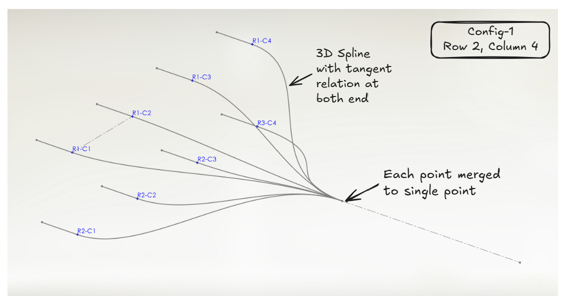
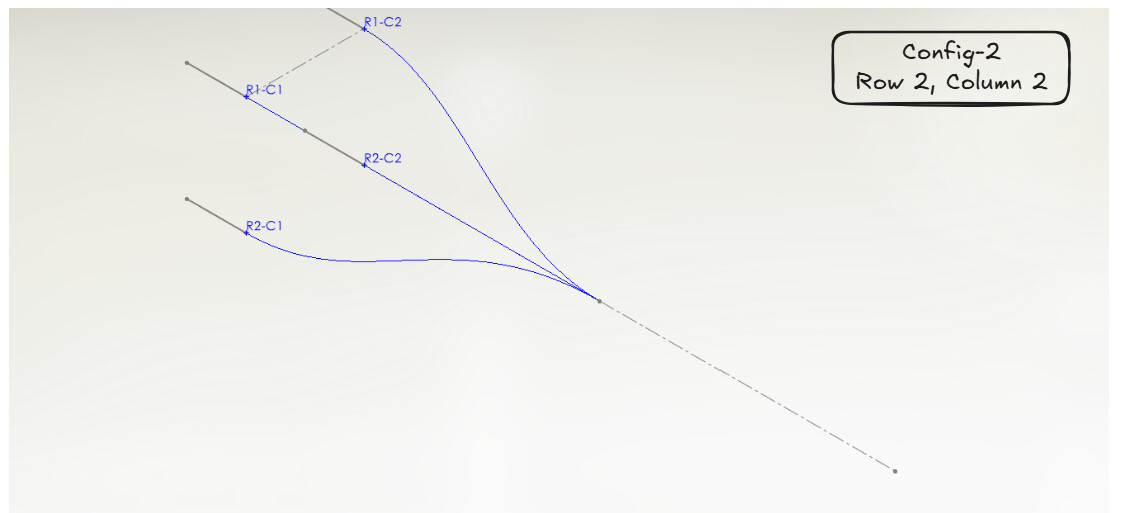
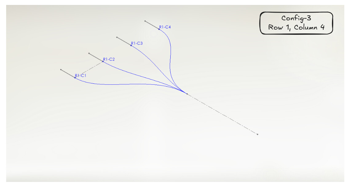
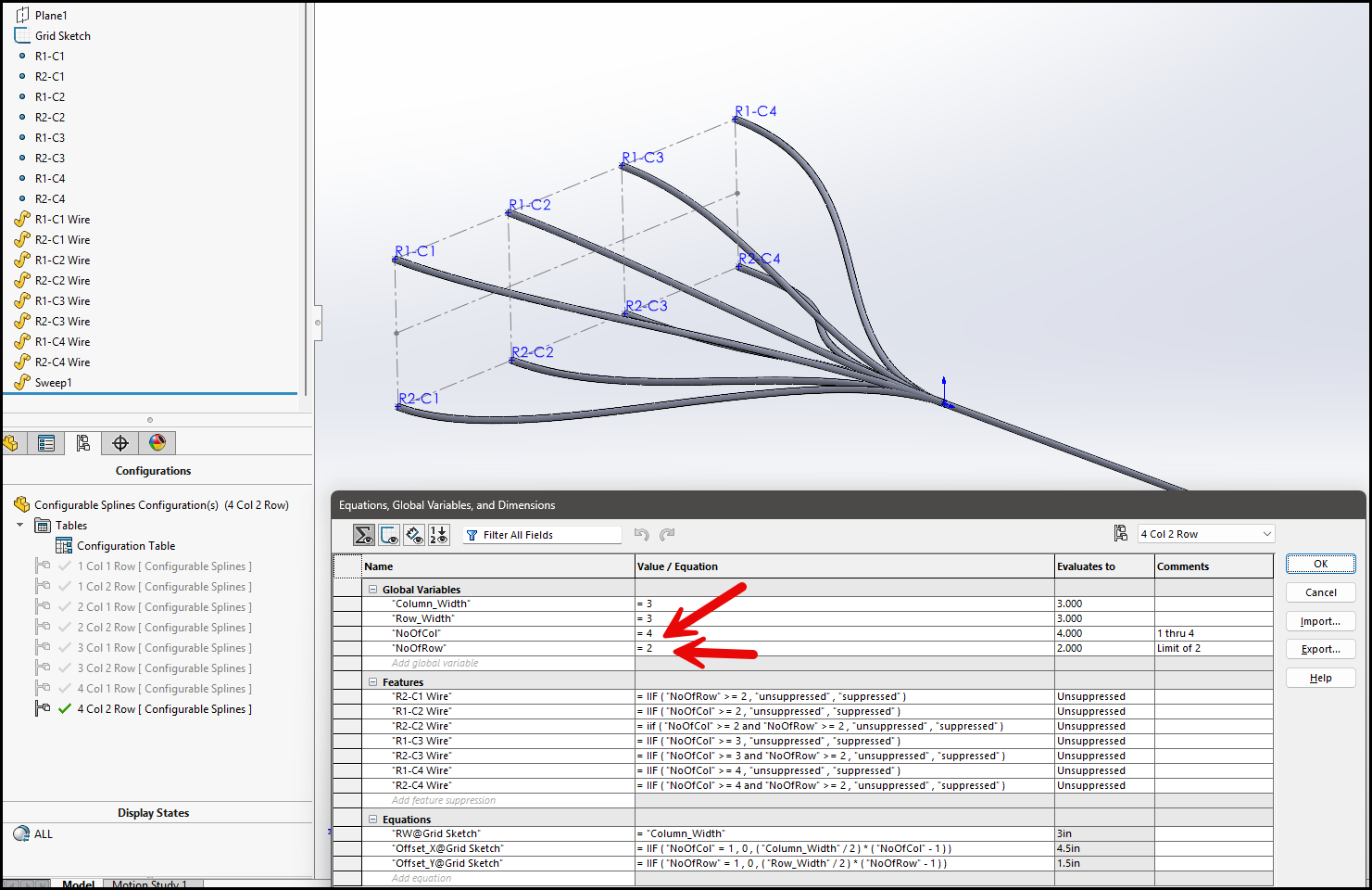
Not sure what problem you’re trying to solve. Looks like wire pathways. Here’s a file, its in 2024 format.
Not sure how many combinations you plan to create. I made equations to control it but you could’ve just manually handled it in a config table or design table. You can change the “number of columns” and “number of rows” variables although I already have them set per configuration.
I am more familiar with Style Splines for this kind of thing. Just three legs (4 nodes), tangency at both ends, and make them equal length. First create the spline in a 3D sketch. Click on one end, make two clicks in space, click on the other end, and hit escape. Set up the tangencies and the equal lengths after that.
I use style splines for just about all spline applications.