image.png
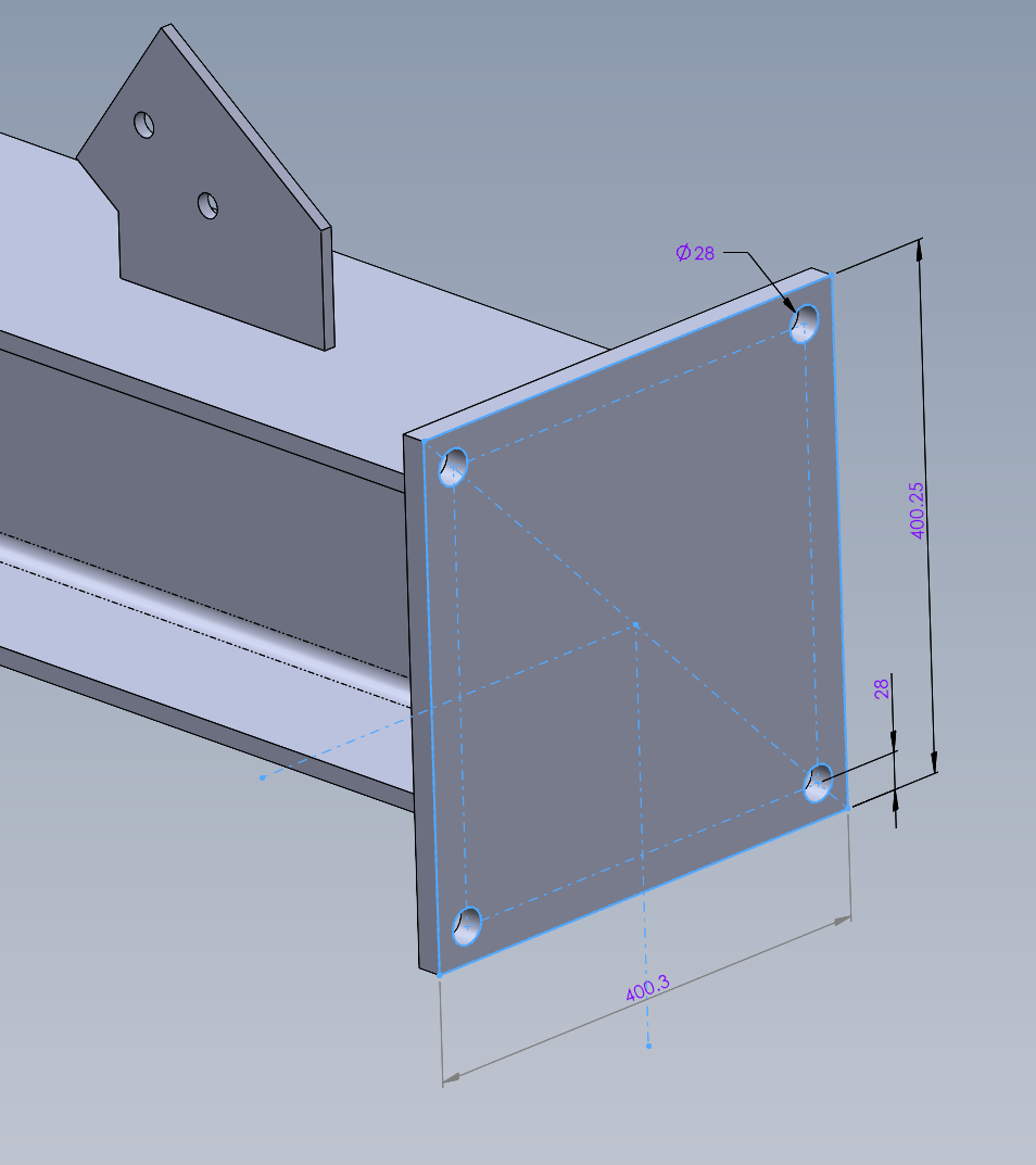
So I have a cut list table in my drawing of tubes for a ladder I am working on, the first two show the length with 2 decimal precision, but the third has only a single decimal value. I delete the table and put in a new one it does the same thing. In the cut-list properties for the part it has a 3 decimal precision

anyone know how to change the value to have more precision?
I am pretty sure that this is a limitation in Solidworks. At least up to Solidworks 2018. I tried to do something similar with a BOM, where I wanted to add a number that represented an items size. However, the precision will always clip out the zeroes.
For some reason, when it comes to tables in Solidworks, if your number is 28.500, then it will always clip to 28.5.
And before I see an argument that they are the same number…they are not. Precision is a factor here.
It’s a round-off. It doesn’t show the 0 and if I’m not mistaken there’s a setting that can be toggled to allow the trailing zeroes to remain.
I understand that the values are rounded off, I would expect that. And on a pipe cut 0.003 is not going to make any difference, the bigger issue is to me is why the first two values show 2 decimal places and the third only shows a single decimal? They all are rounded as the first one is 119.544 and the second one is 103.544 in the properties box. It just looks sloppy and could make a 1/4" difference in tolerance if they go by the default tolerances in the title block. On this part it doesn’t matter, but there might be a time it will.
Yes, I understand that. As I said, the issue comes from a setting in your templates/files that removes trailing zeroes. Change it so that they remain.
Sorry for the frenchness of the screenshot, I think you should understand it though.
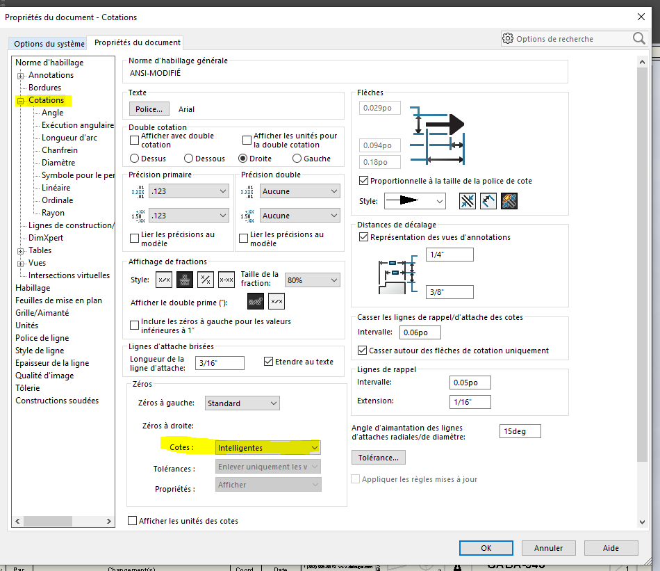
Edit: if it doesn’t change after applying it inside the drawing, try applying the same setting inside the part document.
Moins français.
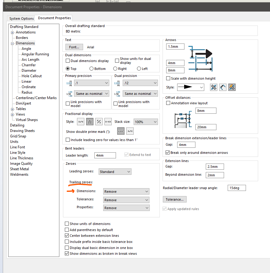
Thanks Dwight ![]()
Have a great weekend!
I have it set to show on the drawing, the only options I have there are show and remove
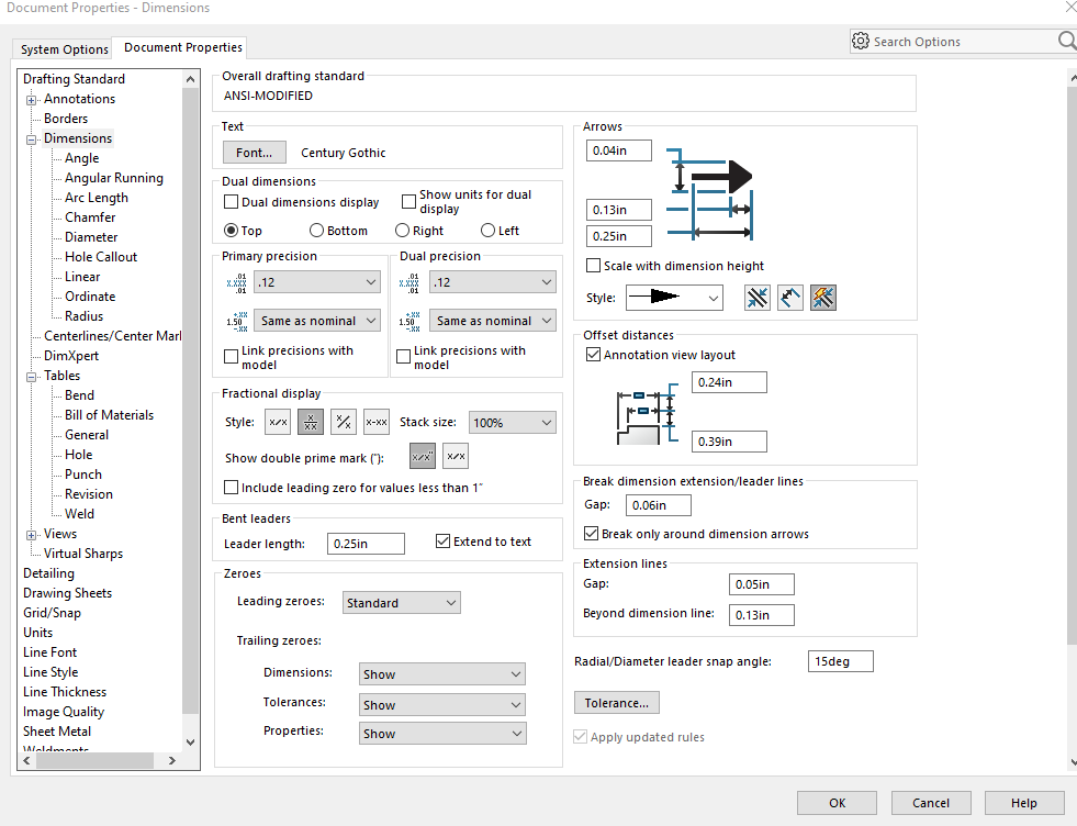
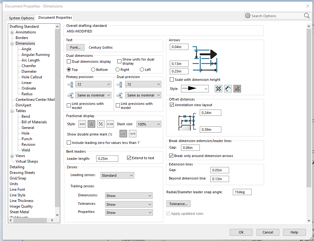
. I only get the smart option on the part file, but it is set to smart there as well. This is it’s rounding to a different decimal place, not dropping zeros. Plus it seems that only pertains to dimensions on the drawings, not the values in the cut list.
Have it set to show on the part rather then the drawing. The properties are at the part level, therefor you need it set on the part’s settings and not the drawings if I remember correctly.
I have the same issue and have tried all these suggestions but have not yet found a solution.
What about the BOM table setting?
image.png
I remembered I posted this question back in May and had the same issue come up on a drawing I am doing today. What jcapriotti posted above works on weld tables as well, but you got to set it on the weld table tab, not BOM tab, DUH!
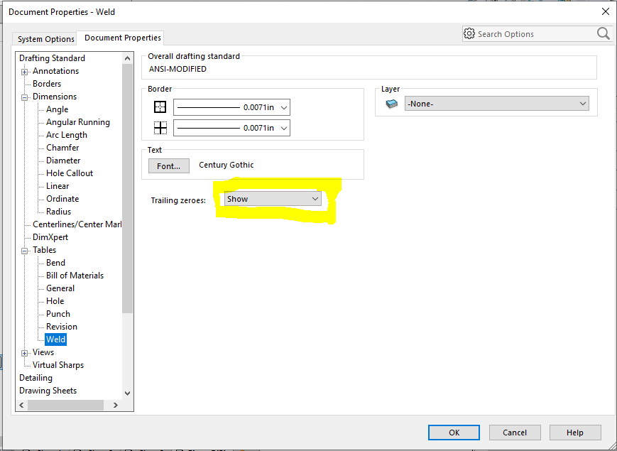
Don’t remember what version it changed on, but the unit precision is now based on the units precision under document properties for the weldment cut list precision.
Old thread, but this is what worked for me just now. Thanks! Adding a bit of info to those who might also come upon this thread searching for the solution. My problem was trying to get trailing zeros to appear for bounding box dims in the cutlist table.
Couple of odd things that threw me off of the trail initially:
-One would think cutlist tables would be covered by the settings under “general”, but indeed the BOM settings worked.
-One would also think that leaving it set to “remove only on zero” (apparently the default) would not suppress the trailing zeros on on-zero values, but that is not the case in this situation.
This is in SW 2023 sp1.0
We recently upgraded to SW 2023, so now I have an issue where the cut list dims keep getting reset back to 6 decimal places. Per above I am setting the units in the drawing under the options tab to 3 decimal places and have show zeros on. When I make any changes to the weldment and refresh the drawing in reverts back to 6 decimal places (Which I believe is the default)
Go back to the model, click the cut length dim, change its precision to none or the decimal places you want
You might want to change the precision of the template you use to do away with the problem in the future
Have you tested this to see if it works?
Yes, especially in SWX 2018
I don’t believe I’ve tried it in this particular situation, but I don’t doubt that it works. I have occasionally seen Part settings override those in Drawings, and the only way to fix the Drawing was to edit the Part properties.
Apologies for my vagueness, there are a few things that can happen here (I’ve just tested a few scenarios in SWX 23)… I think this sums it up, but there may be other situations that could return differently, so your mileage may vary ![]()
If the dimension is the overall length of a member, as in a driven dimension for the element, the dimension precision comes through to the cut list
If the dimension is the overall length of a member that has been trimmed or extended, this dimension comes through from the drawing’s document precision
Below, you can see that the precision is set differently for the two plate lengths, which evaluates as set for the individual dims in the cut list. The component’s document (Basic) units are set to ‘none’
image.png
Here is the cut list with the Basic Units of the drawing document is set to ‘none’… This still shows in the cut list as evaluated at the model level
