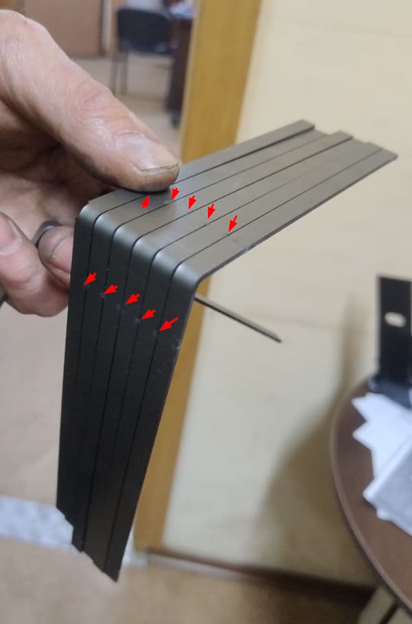
How can I create a sheet metal model that will produce an open cut contour when exported to DXF? This is essentially a laser beam incision that begins cutting the metal at one point and stops at another, leaving a strip with a width equal to the cut width, but in DXF, it simply appears as a segment.
Open geometry should be mapped to layer 0 in DXF, just like regular closed contours.
Making a thin cut and manually deleting segments until only a line remains is not suitable.
Drawing a sketch on the surface that will be mapped to another layer and then transferring it to layer 0 in DXF is not suitable.
Could someone share a working secret on how to create model geometry that will produce this result? Thank you.
The easy way - I would do it in Autocad since I have a license as well as my Solidworks license.
If you need to do it in Soldiworks you can make a sketch in the part with just lines in it that you want and show it on the drawing view, when you export the DXF they will show up in the DXF file.
Here is the sketch in SW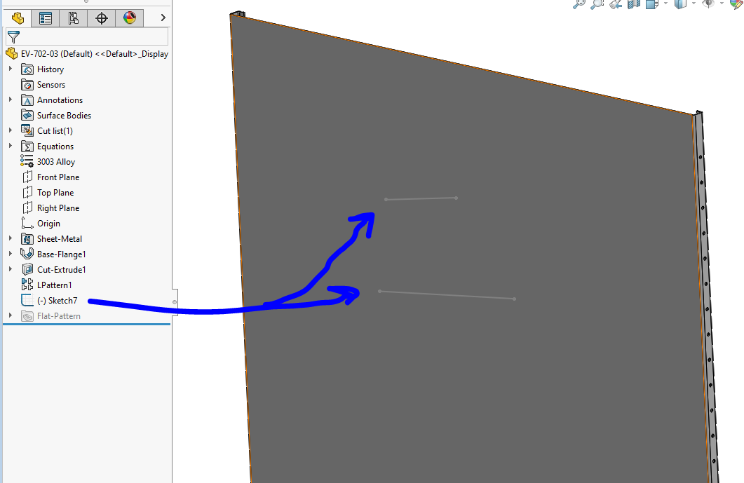
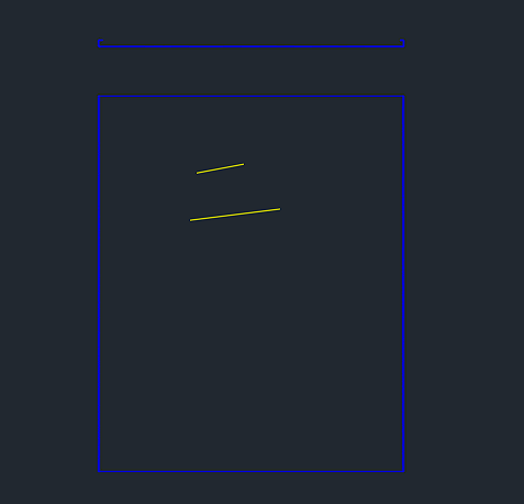
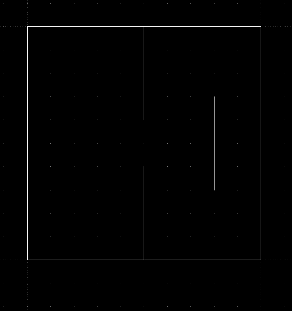
This is my DXF