There are at least three ways to do something very similar in SW.
Set your bolt up with a Mate Reference. When you drag and drop it into an Assembly you can drop it so that concentric and coincident mates are applied (first screenshot). It takes a little practice to get the hang of it, but it works very well.
Grab the edge of the bolt, hold down Alt, and drag it close to the hole (second screenshot). Again, it takes a little practice, but you can drop it so that coincident and concentric mates are applied. It helps if you rotate the components so you can see both edges before first.
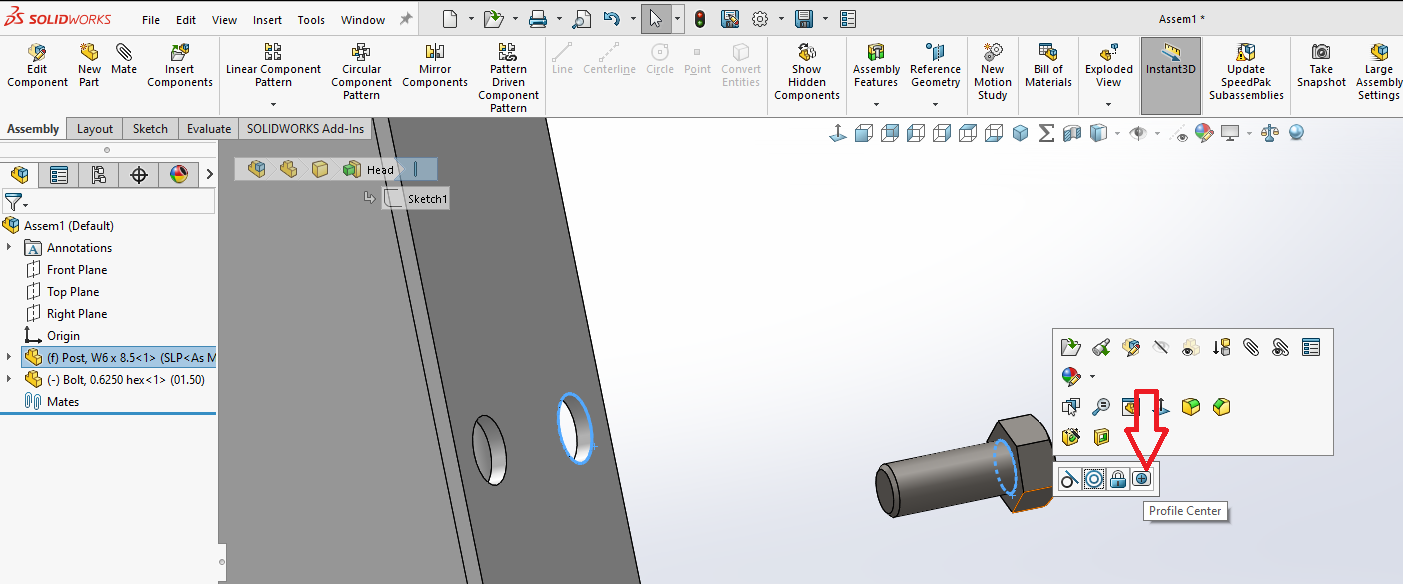
And then there’s my favorite method. Ctrl+select the two edges and apply a Profile Center mate (third screenshot). You can also lock rotation on it, or leave it free to rotate. Of course you can also apply it with the Mate property manager open so you don’t need to Ctrl+select them, but Quick Mates is one of those enhancements I resisted for a year or two, but now use often.
I honestly try and avoid Advanced Mates as much as possible. Not that they cause issues or anything, but they are named Advanced Mates for a reason, they tend to take more time for the program to calculate. If you end up having a huge assembly, it becomes somewhat noticeable.
I had the same problem with a few of my models. It turned out that when I (or whoever) modeled them the head and shaft were two bodies. When I combined them into a single body that problem went away.
Those are the 2 we use most too, but we try to avoid them when possible. As stated, the difference isn’t really noticeable unless you end up with multi-level large assemblies that have a lot of these.
It has to do with what SolidWorks conciders as the direction of the plane/model. I think I remember someone explaining that you could switch the direction with custom made planes, but I don’t think you can change the direction on the 3 original planes.
I usually draw the bolts, screws etc, with the revolve command and it is a single body, the mate is 90% inverted. but tomorrow I will examine what you said, maybe there is an error I missed. Thank you for this information, Uncle.