Need Suggestion for Controlling Patterned CSYS on HVAC chilled water coil Header Plate in SolidWorks

Hi everyone,

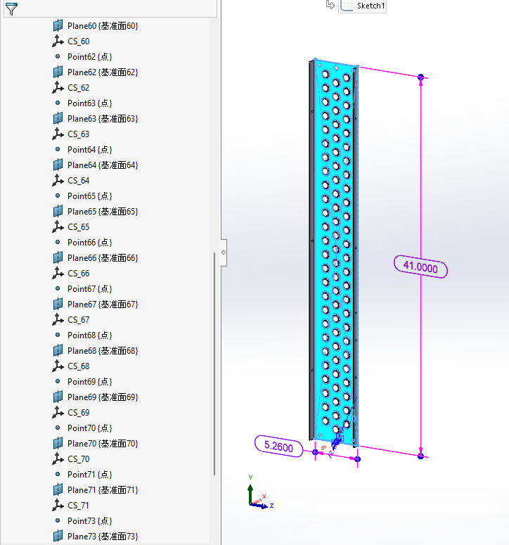
I am currently working on creating coordinate systems (CSYS) on a header plate for each flare hole in SolidWorks and facing an issue with controlling the CSYS pattern.

Current Approach

I am creating the header plate as a start part, where:

  • Height and width of the plate are controlled through a Design Table
  • Flare hole count and pattern are also controlled through the Design Table
  • A CSYS is required on every flare hole for downstream assembly automation

The challenge is that whenever the flare hole count increases or decreases, the corresponding CSYS also needs to automatically suppress/unsuppress.

What I Tried

To overcome this, I:

  1. Created a point sketch pattern based on the flare hole pattern
  2. Created CSYS using those sketch points as references
  3. Controlled CSYS suppression/unsuppression through configurations/design table

Problem

Whenever a CSYS gets unsuppressed, the reference point seems to lose position / shift / go missing, causing the coordinate system reference to fail.

My Question

What would be the best practice to robustly control patterned CSYS when the flare hole count changes dynamically?

Has anyone handled:

  • Pattern-driven CSYS creation
  • Suppression/unsuppression linked to changing feature counts
  • Stable references for CSYS in parametric models?

Any suggestions on a better modeling strategy would be really helpful.

Thanks in advance!

If you can share, what is the problem you are trying to solve by using a Csys on holes?

Hi, thanks for your question.

In my case, the requirement is related to assembly automation.

I have a header plate with multiple flare holes (created using forming tools), and for each hole, I need to create a coordinate system (CSYS). These CSYS are then used as references to mate tubes in the assembly (tube CSYS → header plate CSYS).

The challenge is that the header plate is fully parametric, where:

  • Height and width are controlled through a design table
  • Number of flare holes is also driven through the design table
  • Multiple configurations exist with different hole counts

So, the CSYS count must dynamically adapt to the number of holes.


What I tried:

To avoid managing a large number of CSYS manually in the design table, I:

  • Created a sketch point pattern driven by the flare hole pattern
  • Created CSYS using those sketch points as references
  • Linked the pattern count to the design table

This way, when the hole count changes, the point pattern (and intended CSYS positions) also updates automatically.


Issue I’m facing:

When the hole count increases or decreases and CSYS get unsuppressed,
the reference point becomes unstable / shifts / loses definition, which causes the CSYS to fail.


Main question:

Is there a recommended or robust way to handle CSYS for patterned features in SolidWorks?

Specifically:

  • Can we pattern CSYS directly in SolidWorks (similar to feature patterning)?
  • Or is there a better modeling strategy to ensure:
    • Stable references
    • Automatic update with pattern count
    • No dependency failure when suppressing/unsuppressing
IMO, there are times not to fight the system, but to figure out the best compromise to work within it.

If it were me, I would write a macro that suppressed any existing CSYS, applied new ones based on the current sketch, and stuffed them in a folder named to match the configuration.

This works well if there are a finite number of designs known at the start. It is less helpful if new configurations get added regularly, especially if personnel have to be trained in and follow this methodology.

It sounds like you’ve written yourself into a corner by starting with the problem of inserting a bunch of tubes into an assembly. You’ve solved that problem by writing code to mate tube csys to every csys you find in the header. But I think there’s a good chance that this is not the ideal approach.

Unless the tubes are all different, this should be done with a hole pattern in the header and a feature-driven component pattern in the assembly. There’s only one tube mated to the first hole in the pattern, and then all the rest of the tubes automatically update based on how many holes are in the pattern.

Thanks for the suggestion. Let me share the motivation behind why I am creating a CSYS-to-CSYS mating logic.

The primary goal is to develop a macro that reads the production BOM and automatically creates an assembly by inserting all the required components into a new assembly and mating them based on a CSYS mapping template. The mapping logic is controlled through an Excel template, which defines which part should mate to which component, corresponding CSYS references, orientation, and hierarchy. Different assemblies will have their own dedicated mapping templates.

Regarding the header plate flare hole to tube mating, the challenge is that the tube placement pattern is not always identical. This is an HVAC evaporator coil assembly, where tube placement changes based on the circuit configuration, and the routing/positioning can vary significantly. Through the Excel mapping, we can control which tube mates to which flare hole and at what orientation/angle, making the assembly logic flexible for different circuit designs.

Also, the macro is not being developed only for this evaporator assembly — the objective is to make it generic and scalable for different HVAC unit assemblies, where component relationships and mating logic may vary considerably.

Just wanted to confirm one thing — would it be feasible to develop another macro for automatic CSYS creation at the hole sketch points? I also need to create a reference plane at each hole location to control the tube angle/orientation, so I am exploring whether a macro-driven approach for both CSYS and plane creation would be a robust solution.

Thanks for the suggestion. I agree that fighting SolidWorks rebuild behavior is becoming difficult in this case. Since the flare hole count changes dynamically through the design table, I was trying to avoid macro dependency and control suppression directly. However, regenerating the CSYS based on current sketch points after rebuild sounds like a more robust approach. I will explore whether I can automate the CSYS recreation through VBA while keeping naming consistency for downstream assembly automation.