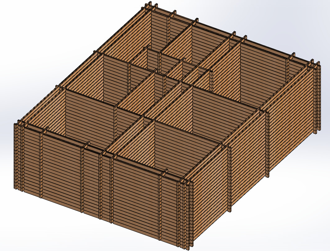
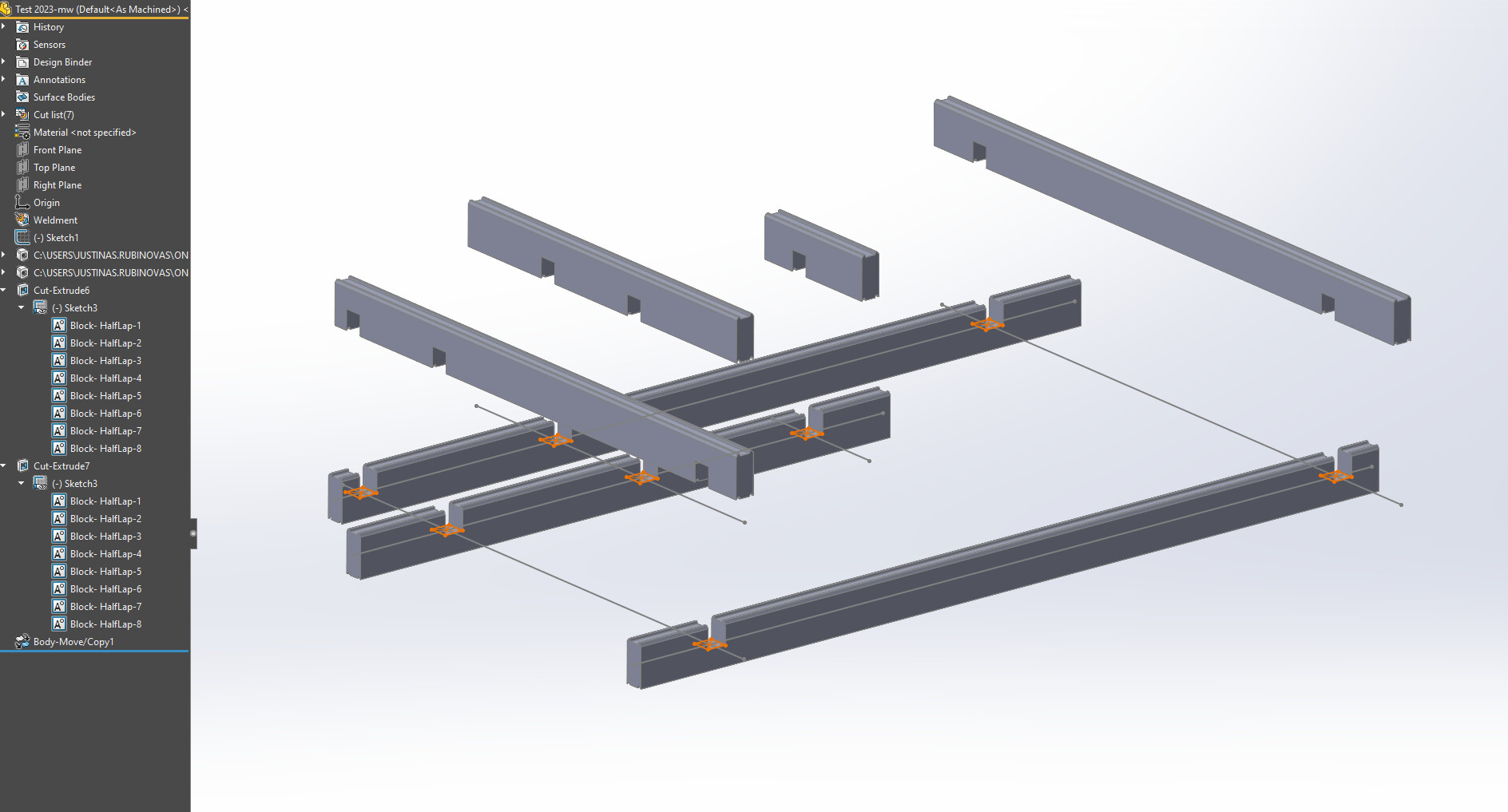
Hey guys, sorry for late reply, I wanted to finish the pilot project before replying. Your suggestions are great, but I don’t see a good way to scale them because of the sheer number and complexity of these joints. If you have the time, please check the assembly and drawing: Upload files for free - Namelis.zip - ufile.io. I’ve done it with Weldments and manual joints in part environment. Assembly only used for smart component stuff (but not for joints).
Notice how many joints there are, and how distinct each beam is. There are 701 bodies in total, and 88 distinct groups of identical bodies. Not all of them are beams, but still, you can imagine that if I tried doing these beams with configurations, then a beam would need to have dozens of configurations, something that would be extremely difficult to set up and manage. Worse of all, it would require great foresight to determine which beams will be unique and which will be the same in advance, almost impossible to do.
With my current implementation, the downsides are:
-
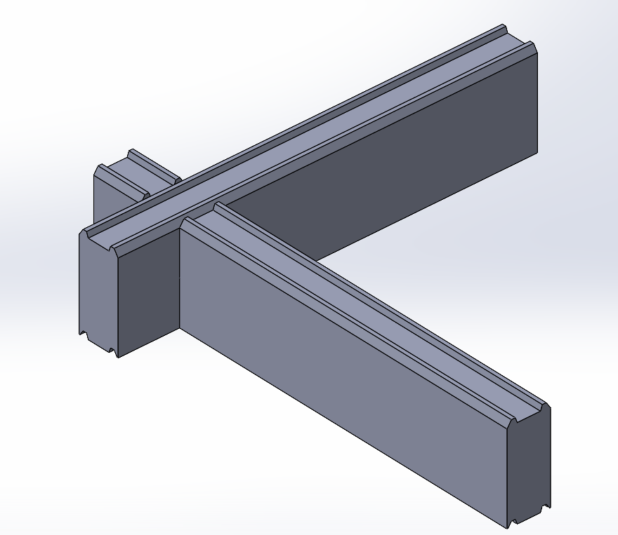
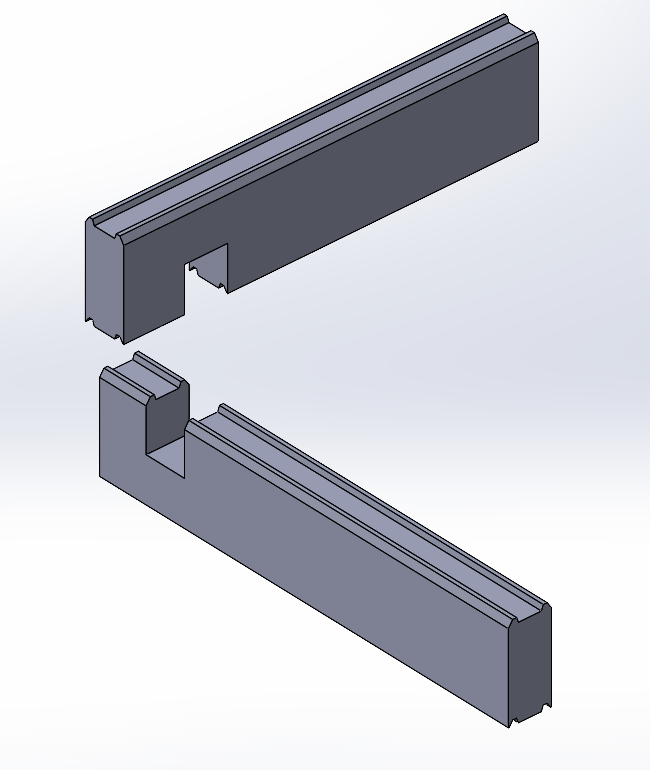
Designing this takes A LOT of time. Each joint has to be done manually. I did utilize multibody cuts and patterns as much as possible, but you can see there are still dozens of joints to manage.
-
It is not flexible. Changing the overall dimensions will change the number of the the bodies (due to dynamic patterns), and many joint cuts will fail due to now pointing to the wrong body. Changing beam type to another size will break references. Almost any change that changes the number of bodies also breaks Display States, requiring lots of repairs to restore the drawings.
-
The rebuild time is super slow even for this very small beam house. For me it takes 24 seconds to do a full rebuild. Imagine doing anything more complicated. Most of that rebuild time is due to joints and Weldment Cut List update figuring out which bodies are unique.
Now, I can imagine that this design could be split into several parts rather than one giant multibody part (for example, have floor/roof/walls split into their own parts), but again, this requires great foresight to know if these parts can really be made separate, because they might need bi-directional links to make joint cuts with the rest of the structure. That only becomes obvious at the very end of the design, and by then it is too late to re-structure (unless you want to re-design from scratch).
I think you can understand this struggle. Can you please take a look at the files, and offer any insights if this could have been done better (not in hindsight, but right from the start when it is still unclear which parts of the design can be independent and which will be interlinked), especially the joints?
P.S. This pilot project is just a test of the modeling workflows, don’t treat it as finished product. It is heavily simplified in many ways and has tons of errors/bad design, it’s just a proof of concept to try and figure out the best way to design such things in SW.