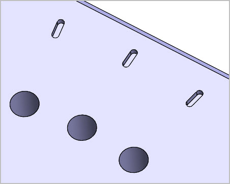
Apologies, not really SW. Wondering if any of you have experience with exporting models to CNC shops on this topic. I require a series of indicator lines corresponding to hole positions. I’ve modelled them as shallow depth slots just because it was easy & makes my eyes happy for now. Guessing a tiny 1mm dia endmill would be kind of silly & more expensive vs. a 90-deg V-cutter weapon of choice? If so, would I generate similar a V-profile, incorporate that in the STEP file or whatever the CNC service requires & they figure it out from there? I dont have any immediate text requirement but would a V-profile be similarly appropriate? (No CNC experience if that wasnt painfully obvious).
I would recommend describing your desired outcome on the 2D drawing, especially if you don’t care a whole lot about the actual dimensions or shape of the indicator lines.
since I’m a machinist I do a lot of this for the CNC and laser cutter.
just make a sketch of what you want, then export either a DXF or Iges of the part.
Step is better, yes, but Iges gives all the sketch data, old way die hard.
What CAM are you using? some bring in native SW along with the sketchs not absorbed into features, Surfcam and Fusion bring them in, thats all I have here.
many ways to skin the cat, sorry PETA 
my world since 1997 with SW and cutting prototype with CNC and CAM
Thanks for replies. This is for a personal hobby part that would benefit from CNC accuracy so I was going to send out CAD file(s) to a few online CNC shops to scope pricing. I do manual machining but no CNC experience. I’m also not familiar with the communication process. Does a bot do rough pricing & a human is available for clarification or additional information? Maybe I should remove the indicator lines from the solid model so its kind of minimum base price but show them on a supplemental PDF drawing saying ‘suggest how you would best do something like this’. I was just assuming a tool change on same cnc setup would be acceptable to me although laser would probably be nicer. Even less familiarity there. I guess this excercise will be as much a test of the service itself.
I believe all the online shops have an option to allow you to upload a PDF or other 2D drawing to have it reviewed. Usually adds some lead time for getting the quote, but I don’t think it adds to the part cost. Alternately, if it’s just a hobby part, how critical are the markings? Can you just scribe them yourself when you get it?
I probably could scribe them myself, but it seems to me it would be a quick tool change to a V-cutter on the cnc & (hopefully) not add much to the base cost. The marks are not deep & not long. And I suppose a bit of gateway to another project where I really would require markings, text, whatever. Its all do-able in CAD, was more wondering about the downstream manufacturing; whate exactly they prefer or require. I’ll stumble my way through it & report back any findings. Again, sory for the not-strictly-CAD discussion.
Xometry, you can download a SW add-in that will allow you to upload the SW part and a drawing with note and tolerences. it will also flag areas that need more clarification or thing that cannot be manufactured like size, shape and features.
best to find a good machine shop in town and either send files or a print and they’ll let you know what they need.
Again ask them, can they take SW files and what version, some have older CAM and only can open older versions on native SW. ask ask ask what they need and then send that.
as a model maker\prototyper for the last 40 years I’ve delt with big ID\Engineering firms and startups, now college students helping them produce first articals, they ask question, I reply and ask some back then the parts get cut.
Laser marking is great, need a fiber laser for metal usually, anodize will mark with CO2 laser or they sell a spray that goes black on non coated metal for use with CO2.
It’s all a good discussion! But it’s hard to know exactly what’s easiest without knowing a lot about the shop that’s actually going to do the work. As Len mentioned, laser marking works well if it’s available, and can be potentially a lot faster and more versatile the more marks you’re making. But if it’s just the 3 little marks from your screenshot, and if the thing’s going to already be in a CNC anyway, it’s likely easier to do with a quick tool swap as you mentioned.
The screen shot was just to show the detail. The holes are 4mm dia, there are 36 of them on this particular model, each hole needs the same radial indicator line. Thanks for the useful comments. My take is that clear communication with CNC shop is the key (no surprise). I could provide with/without groove configurations & accompanying drawing showing ‘lines’ & allow the shop to suggest cost effective solutions specific to their machines.
I’ve also heard that something like a sketch is actually preferred because that gives the programmer a center line to follow & allows flexibility for the tool selection be it a V-shaped engraving bit, tiny ball EM, drag knife… As opposed to if I model the ‘grooves’, then its baked into the export solid & maybe more work for CNC programmer. But I am not clear on how to attach a sketch to a typical CNC friendly file format. I could attach the SW file itself, but that has pros & cons. I can see where Text cold be even more fun! Anyway, good discussion. I’m sure I’ll learn more once I get into the process.
Again, if I was your shop I would have you give me a zip file of
- SolidWorks native part and Drawing
- Step of Part and DXF of Drawing
now reason for both type, maybe my CAM cannot take newer SW but can take Step and DWG.
I can use both in my CAM to get job done.
FYI that shop you go to do these thing daily, trust the process, if they are not sure they will contact you.
if they are using Fusion for CAM if your SW file has open sketch it will come in as it’s own sketch that can be used to generate toolpath, I know cause thats what we use here at ASU.