Hi folks, I’m sure someone has asked this question before, but I’m not sure I’m smart enough to guess the right search terms…
I think this is not the bounding box, but that is the verbage I keep coming up with for it. I have seen many models do this over the years and haven’t found any solution but to crop the view (which sometimes does not work). The red box that surrounds the outer extents of the model has gotten too big in one or more directions. This also impacts the size of view boundaries on drawings.
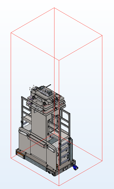
Below is a snip of a model I’m currently working on. The origin is centered on the vertical booms, located near the bottom of the base. I had a piece of stock material forget that it was cut and start shooting up through the top of the machine; that explains the vertical space, but what about the extra space into the screen (towards the back side)?
Is there any way to recover from this or does this drawing just need cropped views for the rest of its life?
That’s often caused by a plane being oversize, or really the graphic that shows a plane being too large. Click on a plane in the feature tree and drag the boundary to make it smaller. Should do the trick.
That is a pain in the @#)$*. Sometimes it is a sketch, or part of a radius that has a center mark way out there in space. Or it could just be some part that is hidden way out there.
I used to open one part at a time. Hit ctrl 7, and see how each part would zoom and then save and close it. One part would not zoom to fit the screen right and then I would dig into it and find what was causing it to be like that.
Here I can repeat the behavior showing a dimension in a part. But I have to show the dim to get it to do this. That is why it is such a pain to figure out why this happens.
So. I knew both of these answers were correct at the core, but how to go about finding them?…
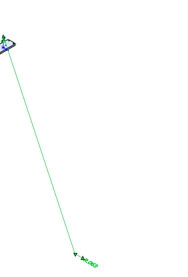
I turned on visibility for sketches, dimensions, annotations, axes, planes, origins, etc. and found a couple funny ones, but no smoking gun. I then switched to my front view and did a drag-select over the area where nothing was. And wouldn’t you know, my PDM pane selected something. It was a virtual assembly for a hydraulic hose (we place hose ends where they belong, create a virtual assembly, then within that virtual assembly, we sweep the hose diameter along a path). At some point, the origin of the parent model moved significantly, so when you open the model of the hose, the ends were floating in the air way above the hose part. This is due to the way mates are applied; in the virtual subassembly, nothing is defined in space. I grabbed the planes, shrunk them down, then grabbed the hose ends and dragged them down to the hose and it looks like my extents are once again the extents of the model I can see!