I’m working on a scissor lift type structure with two symmetrical “legs”. I modeled the legs as a subassembly by constructing one of them and then mirroring them about the front plane. The original set of components is fully defined and positioned with a distance mate to the front plane of the assembly. In it’s subassembly it works just fine, the issues come when that subassembly is placed into the top level. The subassembly with the two scissor lift legs is mated into the top level with a coincident mate between the front plane of the subassembly and the front plane of the top level (such that the two legs are symmetric and centered in the top level). For some reason, the components of the subassembly which are mirrored are free to move closer to or further from the front plane, and mates to the mirrored components are completely ignored. They aren’t broken, or overdefining the assembly, they just aren’t actually constraining the parts; the end of the last link of the scissor mechanism is mated concentric to the inner race of the bearings that they will eventually be pinned to, but the legs are freely moving in and out of concentricity with the bearings. The manually built side of the subassembly isn’t exhibiting any of this, and is acting normally. It’s super weird and also somehow not showing any warnings or errors while this is happening and I’m really confused. Any ideas of how to fix this or places to start in troubleshooting are much appreciated. Thanks!
Are you working with flexible assemblies/sub-assemblies? Could you post screenshots to show the featuremanager and the issue as well, if you can’t share the file..? That might make it easier to find the root cause, it’s hard to determine what could be the issue from what you said alone.
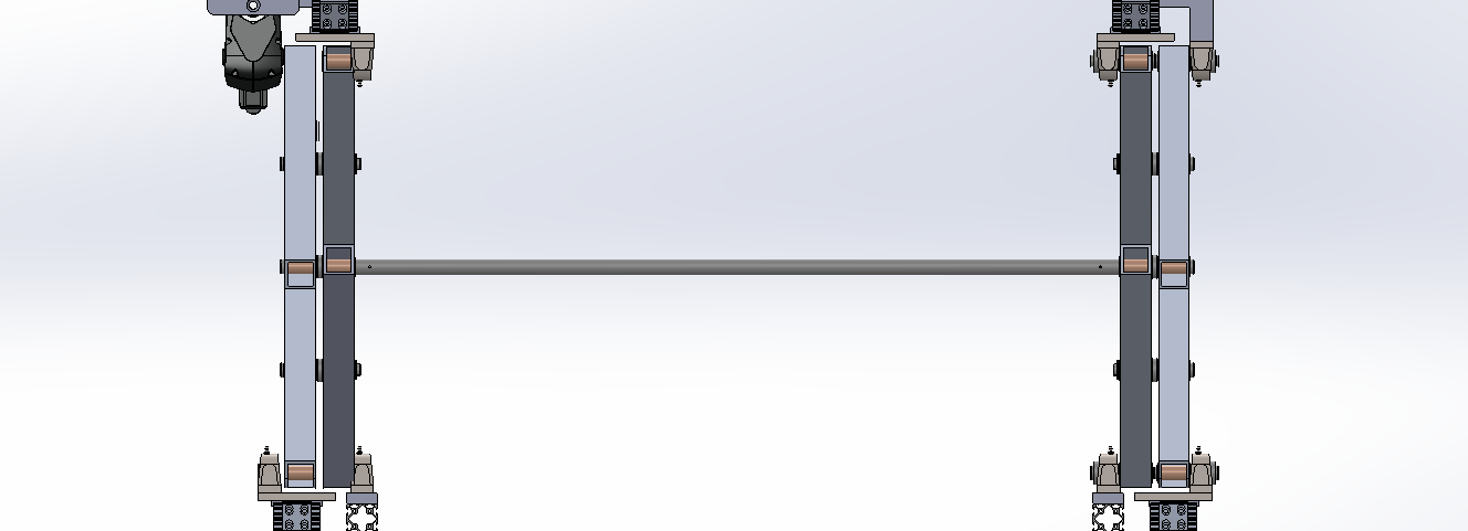
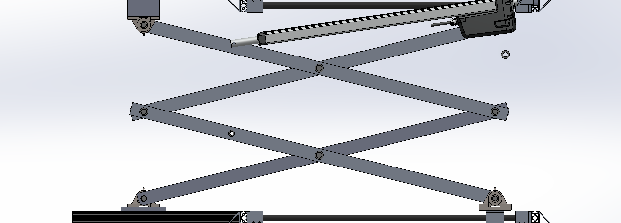
There are three subassemblies total, all of which are set to flexible. After further investigation, the scissor subassembly is perfectly content to operate as intended and will not exhibit the side to side behavior up until the point that any hardware is mated to the mirrored side, at which point it seems to decouple somehow and become movable. I’ve attached some pictures showing the assembly and an example of the movement, as well as used the measure tool to confirm that it is in fact the mirrored components moving and not something else in the top level. With the interference shown in the picture of the bearing housing and top leg pivot, the two legs are actually 0.23in closer together than they are in the subassembly. It happens whenever I put a coincident mate between a washer (which has no other mates) and the mirrored scissor leg; it just decides to move the leg instead of the washer.
I don’t think I could show the whole feature tree without renaming most of it for confidentiality reasons, but if there is a specific subset of it that would be helpful in diagnosing this then I could edit just that part and post.
I agree, I don’t* mirror symmetrical parts, just insert another instance of the part. My main reason to avoid mirroring is that mating an additional instance of the part/sub-assembly will verify it is symmetrical. Plus it’s easier to check if changes will affect the symmetry of the assembly.
As I said above, mating inserted components to patterned components often produces unpleasant results. If this hardware is also in the original assembly I would suggest mirroring it in the mirrored assembly also instead of inserting and mating it. If it isn’t, one option would be to have two configurations of that sub-assembly, one with the hardware and one without it, then reference the appropriate configuration in each instance in the upper level assembly.
One “hack” I’ve learned with mirrored sub-assemblies is not to mirror them at the top level, rather create a configuration within the sub-assembly itself, mirror the parts about the plane of choice (for opposite hand version parts, I always choose “create a derived configuration” , rather than a new file) and then use the envelope function to effectively “turn off” the seed parts, leaving only the mirrored parts active in the mirrored configuration I created. Then I’ll just insert a that sub-assembly into my top level, and mate as another instance. Linking display states to your configuration is required.
In terms of stability and predictability, I’ve had good success with this approach, especially when design changes are made. The use of envelopes leaves all references active, whereas suppressing those seed parts would not.
Yep. Just did a test and had no issues with either configuration moving when the “make assembly flexible” option was selected.
The mirrored configuration would have the same behavior as the source configuration, and again, because envelopes keep all references active, no strange behavior should occur.
May I ask why you don’t just have multiple display states of the sub-assembly, and reference the desired one in the main assembly? That way you wouldn’t need multiple configurations, or envelope components.