In an .SLDDRW, I’ll often use “Link to Property” to dynamically show the weight of the part or assembly in the title block.
Say I have a part with multiple configurations, each with its own weight defined in Configuration Properties (please see below). How would I call those Configuration Properties individually from the .SLDDRW?
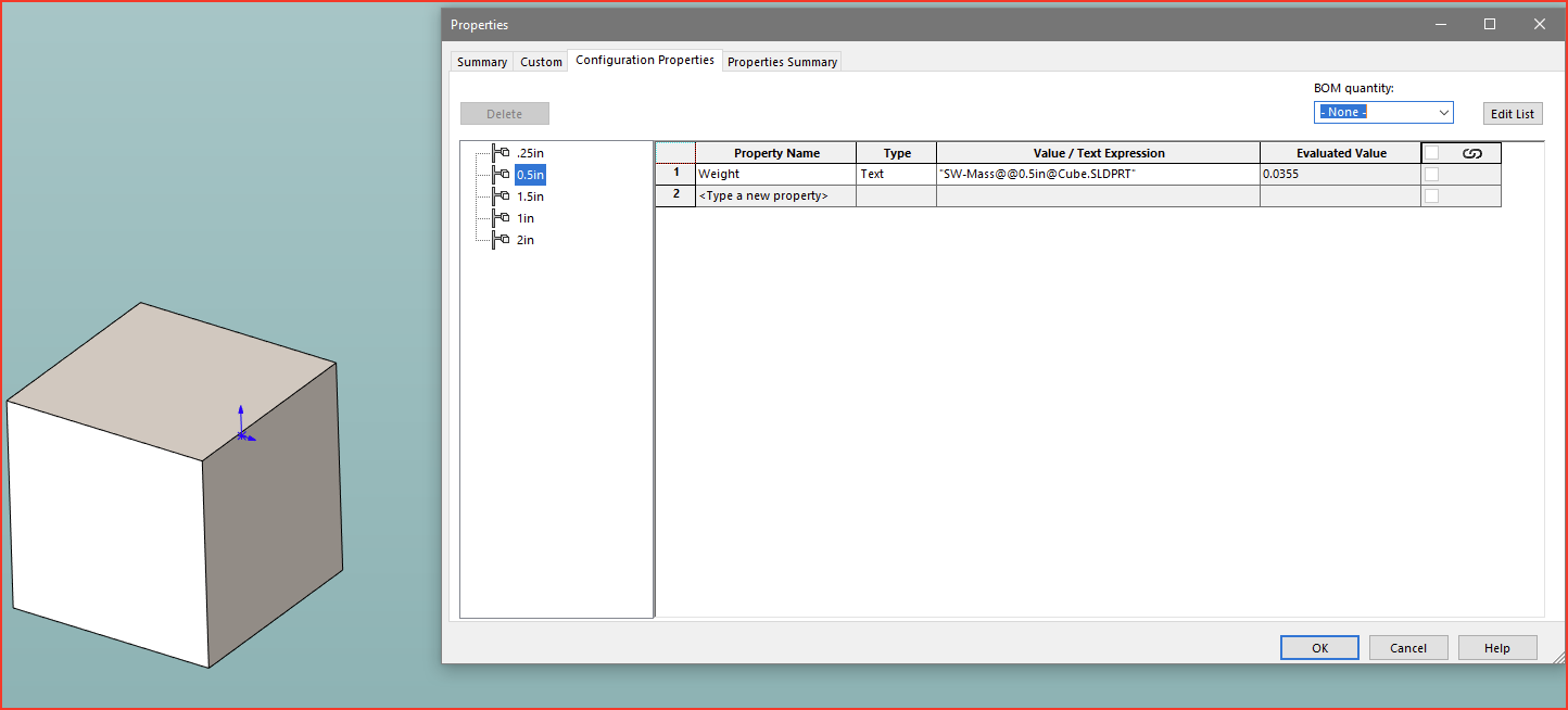
At the part level, make sure that you have your weights set up in the “Configurations Properties tab”:
image.png
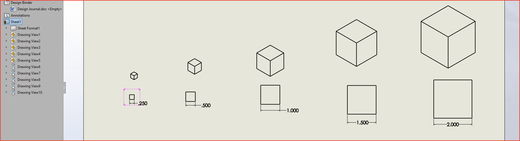
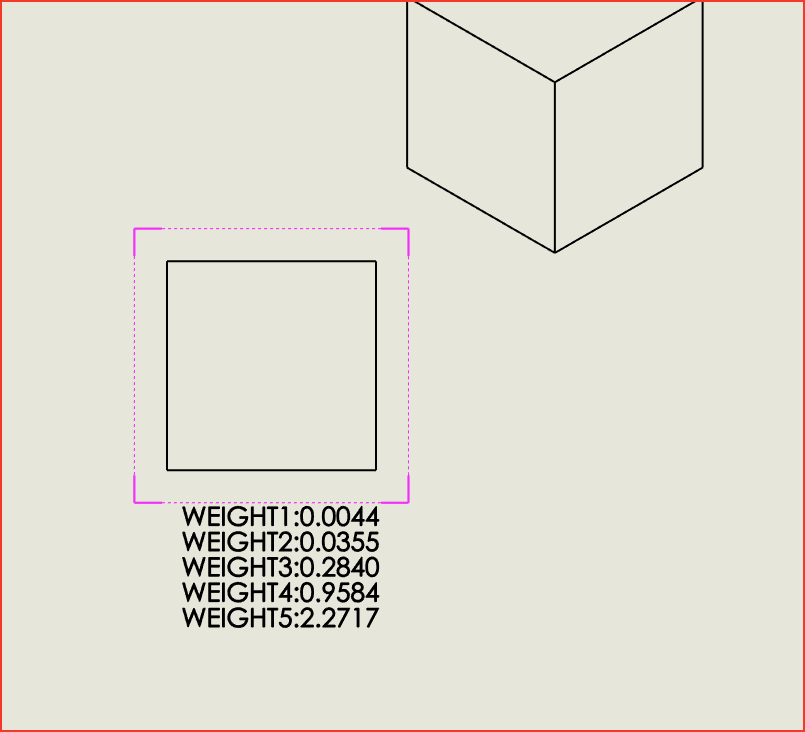
Then, at your drawing level, create at least one view with each configuration in it:
image.png
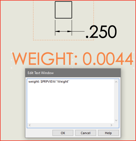
Then you can insert a note into each view:
Then, inside the Link to property, make sure your settings are like this:
Then you can copy and paste that same note into each view (make sure that you “activate” the view before you paste so that the note is “inside” the view).
Edit: The actual syntax for inserting the property (which you don’t really need if you use the above steps, but in case you wanted to see it):
Thanks. I was hoping to avoid having each configuration in my drawing, though.
The particular part in question is a weldment that has a 6" OD tube that can be cut to various lengths. I have an “L” dimension and a table that defines it for different part numbers. For the dimensioned drawing, I chose the shortest length to work with.
Wish there was a way to insert a “Configuration” table that are similar to BOM/Weldment tables. Only option is to create an Excel Design table and insert it. Usually too much work formatting and hiding the syntax rows and columns you don’t want to see IMO.
Agreed. Design table can do it. But it looks horrible and and is a giant pain to get it to look right.
Basically it is just a screen shot of whatever your design table looks like the last time you edited it at the part level. Complete with all the stupid little symbols that excel shows in the top left corner of each cell.
In my opinion is it WAY more work trying to get your excel design table to look right on the drawing than it is to simply add views of each of your configs, add a note to each view, then move the views off the sheet but drag your notes back onto the sheet in a defined order.
Well. There is actually. But it requires some work from you.
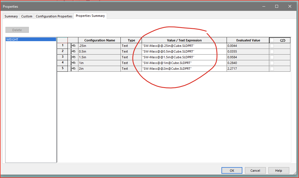
In your properties summary, you have these:
image.png
If you create separate custom properties for each of the configurations, then copy and paste the text from each of the “properties summary” tab line items, then you can make it work:
image.png
Then, at your drawing level, you can link to each of the custom properties.:
So, it isn’t great, but its doable.
I’m not at all sure I followed what you’re trying to do, so this may or may not help, but you can have Part custom properties and configuration properties with the same name. When referencing the property in the Drawing it will use the Part property, but it there’s a configuration property with the same name it will reference that instead.