My best advice regarding sketch patterns is to not use them. Create one instance in the sketch, then pattern the feature or body. There may be cases where this isn’t good advice, but I’ve been using SW for 30+ hours per week since 2009 and I’ve never run into one.
Patterning features instead of sketch entities is easier to edit, easier to control with configurations, more stable, . . . you get the idea.
Mirroring sketch entities, on the other hand, works very well, and I do it often.
Edit: Just because I haven’t run into a case in my work doesn’t mean there aren’t any. See the responses below, especially the ones from josh.
I will change my advice to say that in most cases patterning the feature or body is a better choice. It’s like using a 3d sketch. They’re more difficult to deal with than 2d sketches, especially for someone new to the software, but they have their uses. However, all too often people try to use them when two simpler 2d sketches (or sometimes even one) would be a better choice.
It boils down to don’t use one unless you really need one. In most cases (but not all), you don’t.
How about one instance in the sketch, extrude/revolve/loft/sweep as a new body, pattern the body, then Boolean back to the base body or add to a more complicated tool body that will then be cut or union with base body. I have found this method to be one of the most robust when it comes to editing future revisions. It was also no worse than other methods at dropping geometry IDs so edits done carefully were less apt to break mates and dangle drawing annotations; that was in edge, haven’t been in SW long enough to figure out what things cause geometry IDs to change. I swear looking at a sketch will change them sometimes.
It was so long ago that I don’t remember, and judging from the number of posts I’ve seen on various forums through the years I have no desire to re-visit them. I wrote this blog post so I’d have something to link to in response to those posts in the future.
If you’re going to be pointing people to this advice, then there should be a tempering voice here . You should work to understand both and how they work, and use them when appropriate. I do agree that feature patterns are better most of the time, but sketch patterns have their use. Understanding both tools is objectively superior to ignoring one and using the other exclusively. You said you’ve never encountered a situation where sketch patterns are better… But you also said that you’ve never used them and don’t really understand how they work. Considering that, it’s unlikely that you would recognize such a situation should it occur.
If your advice is, “Step back and consider if a feature pattern would work better here” I can agree. I cannot agree with “Ignore the fact that sketch patterns exist”.
That’s fair, and I will try to be more open-minded, but I still contend that most of the problems with them I see people posting about could be solved by patterning the feature instead.
Not to help pick Glenn’s point apart, because frankly I’m in the “Don’t bother using sketch patterns” camp too, but do you happen to have any good examples of sketch patterns handy? Or does anyone has a link to a >good< application of sketch pattern. Not some VAR blog of “look how to use a sketch pattern” but rather, here’s a case where you’re better off using a pattern in the sketch than trying to pattern a feature or body and here’s why" type of blog.
That probably sounds like a challenge trying to prove that there are none, but that is truly not the case. I’m assuming there are good scenarios like I described, I just can’t think of any. But that’s probably just because I don’t know that much and my experience is mostly in one type of use case. Which would lead to this kind of a conclusion, because we all know my perception >is< reality, right?
Oh yeah, SSP method. Have only used in hands on demo/training long ago.
So if I understand correctly the sketch will never be used to directly make a solid, but rather control other parts in the master assembly. Those other part files with the solids will have their own sketches (driven by this one) from which the solids are extruded, revolved, etc.? Or is this sketch with pattern only used by mates at the assembly level?
The sketch pattern is then used to do a sketch driven pattern feature in a part that will drive more pattern features later up the tree.
Another example is using the hole feature. Why would you create one hole and then pattern it rather then have a sketch pattern inside the hole feature?
I think the best reason to realize why sketch patterns have their use is that people often use sketch driven patterns and at times you can include certain patterns inside that specific sketch.
We use sketch driven patterns all the time and the biggest mistake people make is they forget that the feature that is being patterned cannot be placed over a sketch point, it needs to be placed on a line endpoint or something along that line or else the sketch point counts as an occurence. Then, they end up with a pattern that adds an extra occurence and do not understand why.
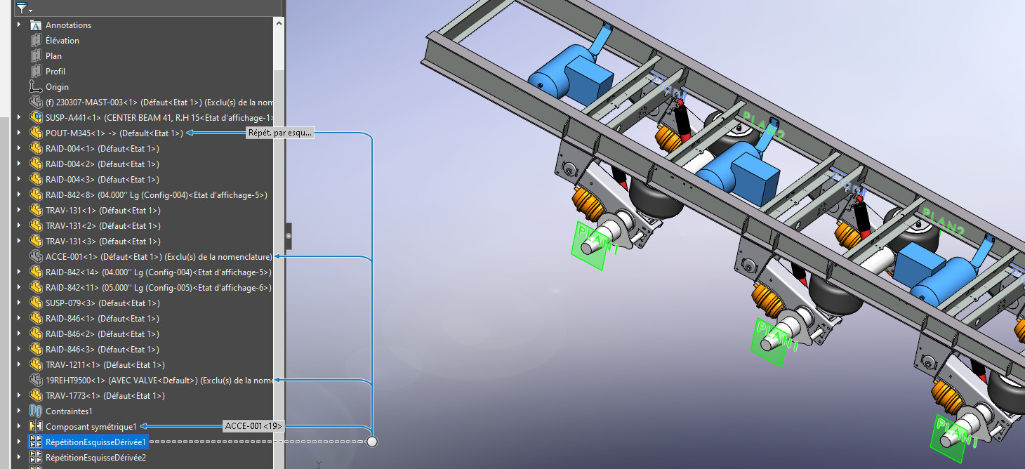
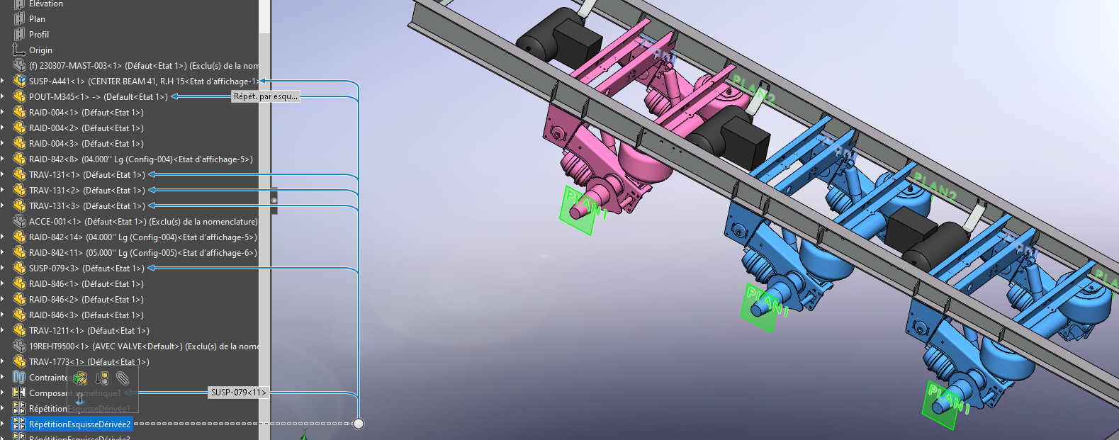
A picture is worth a thousand words I guess. Here’s an example of a co-worker that created a sketch driven pattern but used a sketch point to drive the original occurence. Which is why everything shown are occurences and the parts that are patterned are hidden and excluded from the BOM. Second picture shows a sketch driven pattern done correctly.
Picture 1: Sketch driven pattern done wrong
It sounds like the patterned sketch elements are used to position features and not to define profiles or regions to extrude/revolve/etc?
Also, these sound like products that are highly configurable vs highly customized?
Indeed. They are used to position features and sometimes the sketch contains shapes such as the circle shown that represent the size of the tire. I’ve added a bit more context in my previous post.
Can you use a sketch pattern to drive a Pattern Driven Component Pattern in an assembly? If not, that’s one reason. (In the interest of full disclosure I usually use Hole Wizard features to drive those instead of a linear pattern, but not always.)
Yes, that is a derived sketch driven pattern in the images above, which means it’s a sketch pattern that created a feature pattern and that has another pattern feature that uses it as a a reference.
I think one struggle point of sketch patterns vs feature patterns is the fact that sketch patterns aren’t always fully locked in by default. When you make a feature pattern, and you check that box, the yellow preview immediately turns into hard, fully defined geometry. Ain’t nothing moving around. With sketch patterns, depending on which boxes you check in the property manager, the resulting sketch geometry may or may not be fully defined. As long as you know what to expect, this flexibility can be pretty powerful
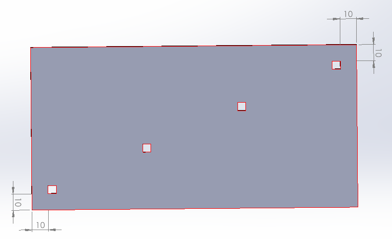
Here’s a quickie example of something that I think is easier to do with a sketch pattern vs a feature pattern. Granted, it’s not a real life part, but bear with me. The design concept is four rectangular holes on a diagonal, with the outer holes always 10mm away from the edge no matter what size the plate becomes and no matter what size the holes are. I did it by making a sketch pattern and leaving all of the “constraining” boxes un-checked in the pattern property manager. The pattern direction was unconstrained. The spacing was unconstrained. The only constraint was that there are four of them, and they’re in a line. I got to add the rest of the constraints I wanted.
I’d be interested to see how one would achieve this with a feature pattern. I played around with the “up to reference” for a bit, but didn’t really see how it would be done without adding a bunch of construction geometry or something. It’s quite possible that I just missed the easy button on it. I hope you don’t see this as being argumentative… I just want everyone to have as many tools in their arsenal as possible.
I didn’t see your responses as being argumentative. I’d like to think my ego isn’t so fragile that it can’t take criticism. What do you (and others) think of the edit?
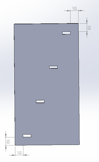
I’m not sure this works… Spec is for the edge of the bottom-right and upper-left rectangular holes to be 10mm from the nearest edge, no matter what size the plate is or what size the rectangular holes are.
image.png
One thing I thought of was to use a 2-direction pattern and then select the un-needed instances to skip, since that would allow you two “up to” references. But I still didn’t see how to make the patterned instances stay 10mm from the edge, no matter how big the rectangular hole is.