In engineering work, there is a task when you are sent a photo of some structure with a ruler attached to it. And as a result, you have one or more characteristic dimensions and a photo in perspective.
Often in this photo there are lines that are parallel in the real world, but in the photo they converge in perspective and they can be used to set the camera (with perspective) that will look at our photo as the camera did. And using the characteristic dimensions in the photo, you can adjust the scale of the coordinates. Which will ultimately allow you to measure all the other missing dimensions from the photo and make a 3D model.
Are there any applications that can do this? Something similar happens in the video SOLIDWORKS 2022 What’s New - Visualize from 1:05
Camera Matchingadjusts a camera viewpoint so that the perspective in a background image matches the perspective of the 3D world. This allows you to place 3D objects as if they were part of the background image.
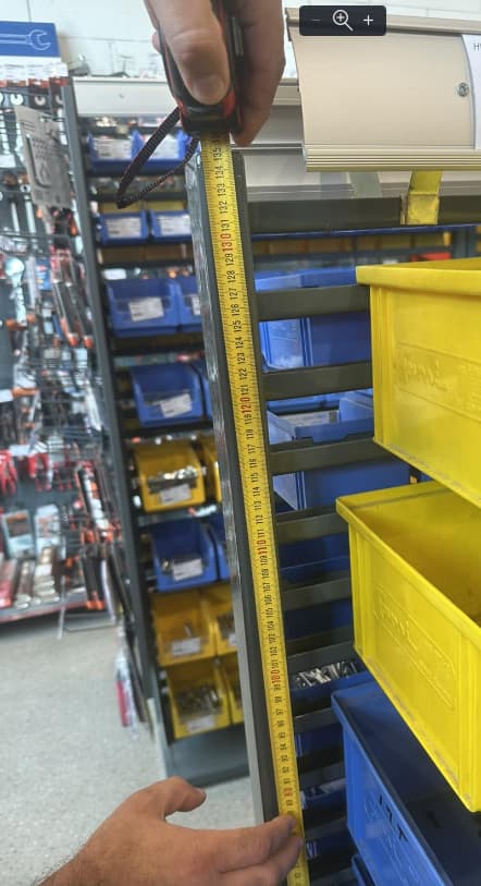
Photos are a great way to get dimensions when you are trying to model something that has been built. I would take soap stone out to the field with me or a non permanent marker and write the dims on the parts if I had to measure things. Then get photos. Other times I would just put the tape out and just take photos of the tape trying to be sure to get the starting point and then close ups of the dims that were needed.
The other thing I would do when I found a good video editor was to take video of the tape laying out over the parts. When possible I really like to get the video of the assembly process and the dimensions that the shop were trying to use to put the assembly together as a finished product was never consistent with the same dims. ( welded assemblies)
Take the photo as straight on the part as possible. Keep what you need at the center and no more then 1/2 the width/height of the photo. Don’t fill it to the edge, it’ll be distorted.
Don’t use 2” of the tape. Fill the view with the tape.
Insert photo in sketch and scale it to match the tape.
Photoshop can distort an image by perspective, among other things. It’ll be by eye. In the situation shown in your example, the vertical scale will be good, but horizontally it’ll be guesswork. Best to have more dimensions.
fSpy computes the approximate focal length, orientation and position of the camera in 3D space based on user defined control points in still images. The computed camera parameters can be used in other apps, for example 3D modeling tools.
Adobe Lightroom, Photoshop, and Camera RAW all have the ability to extract EXIF data from an image and then apply a lens distortion correction (this fixes pincushion). This automatic correction is pretty slick but does require EXIF data. Photoshop also have the ability to set a square reference frame and then use the translation tool with “perspective” translation, and you can pull it and shape it until all perspective lines are parallel.
I do not know if GIMP has the ability to extract lens distortion data, but it is free and can also do the second half of perspective adjustments.
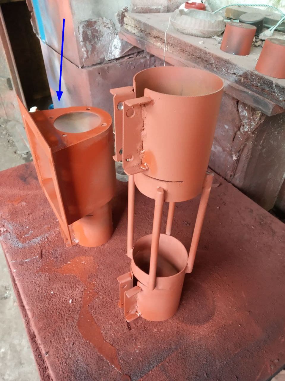
There are many different options. Okay, how would you make a model of the funnel shown in the photo with the blue arrow? Considering that we have an exact DXF flange, where can we get the flange dimensions?
The photo shows very good objects with basic parallel edges (the base on which everything stands).
If you have the dxf for the main flange. Bring it into a part and make a solid out of it. Then work off of that to make the rest of the part. I think it would go with a solid body construction.
With out accurate dimensions or a way to physically measure the part, it is a lot of WAG you will have to do. (Wild A$$ Guess) but if you can send the drawing you make to where the part is they could measure it and mark up the drawing.