I use planes, mostly primary but reference ones too, when creating parts. When I come to use these parts in an assembly, I would like to have them hidden to avoid clutter in the display of the assembly. I know you can hide them. However, whenever you do that, it also hides them in the part file!
Is there a way to have them shown in the part, but hidden in the assembly at the same time?
Will it work to turn planes of in the assembly by leaving the plane visibility off in the assembly? That is the way we do it here. On in the part but then in the assembly they are off.
In the assembly if for some reason you want to show the planes for matting references I would use the Isolate command to show the main components that you want to mate and have the planes shown, and then turn them off when done.
Maybe take a look at the template to see if you have them turned on when you start a new assembly. if you don’t want to see them.
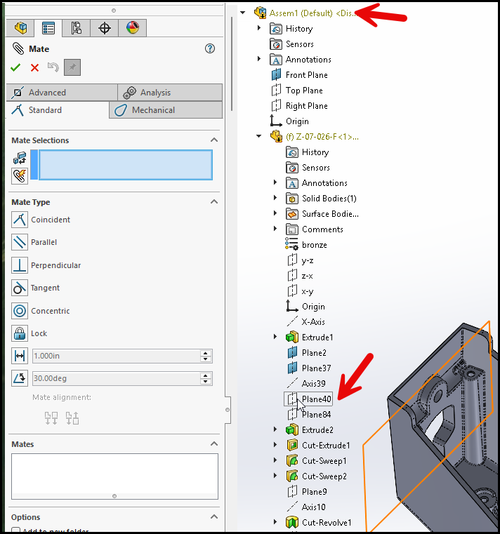
When I am modeling a part, I pick planes from the feature tree, not the graphics window. That way I can hide them in the model and assemblies are not filled with a cloud of planes (though you can show one temporarily when you need it).
Thanks for the response! But wouldn’t this also stop displaying all planes in the assembly? Ideally, planes associated with a part would not show in an assembly, but the planes associated with the assembly would. Not sure I explain this right?
It seems that this is a good way of approaching this issue. I originally trained in Pro/E and the use of reference planes and axes was extensive, as it gives you more freedom rather than referencing features to lines/edges on a part (think of a feature collapsing because you reference it to an edge that got filleted, chamfered, cut, etc, at a later stage!). Keeping the planes displayed when you open the part but not when the part is used in an assembly was common in Pro/E.
Thanks for the answers, I feel we will follow suit and make this also best practice here!
We also build custom truck service bodies & for that we have a part that we start with that has quite a few “skeleton” planes in it. We can then hide or unhide that part in the assembly as needed.
Not sure how Creo handles this as I’ve never used it, but in SolidWorks I do select planes, axis, and other ref geometry extensively. I just use the flayout tree to select them instead of showing them and selecting from the graphics window.
as a machinist it really helps quickly show all different looks in a part and even more in an assembly using CAM inside of SW. you just hide and show in the default config.