you could manually rotate the views and save them into your template.
SW has some default standard views, that fit most use cases, but there are places that prefer to use a dimetric projection or others in place of isometric.
Including all the possibilities in the software would be eccessive, api and macros are there for that reason.
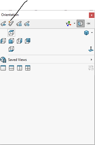
As a workaround, you can use the space bar to select your named view, and then immediately create a new named view, giving it the correct name and then delete the original. Not ideal if you have to update a bunch of drawings, of course.
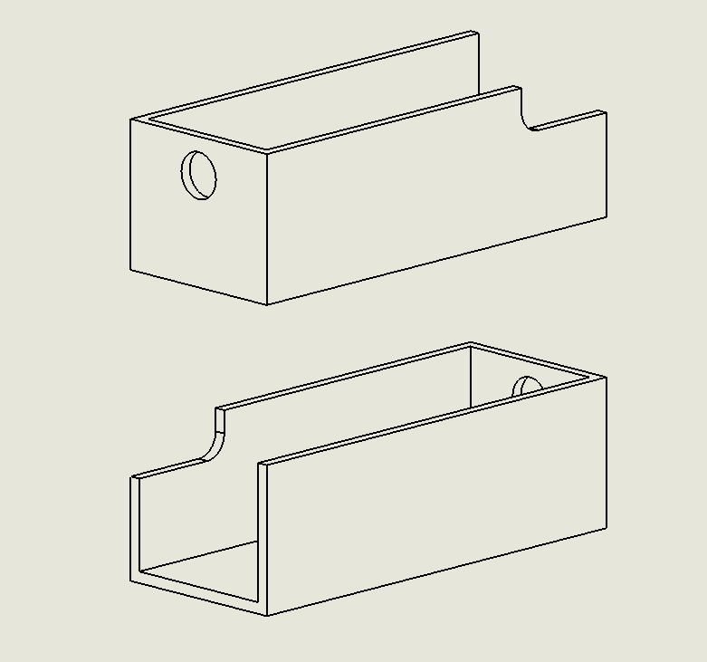
Our parts are often long and narrow. I make my own ‘nicer’ (IMO) iso views that fit on the sheet better by taking up less room on the sheet and are a bit less extreme perspective. iso1, iso2, iso3, etc…
Choose a view of the part that is oriented more towards landscape. If the part is more portrait oriented, use the ALT-arrow kets to rotate it more horizontally (default alt-arrow is 15° per click)
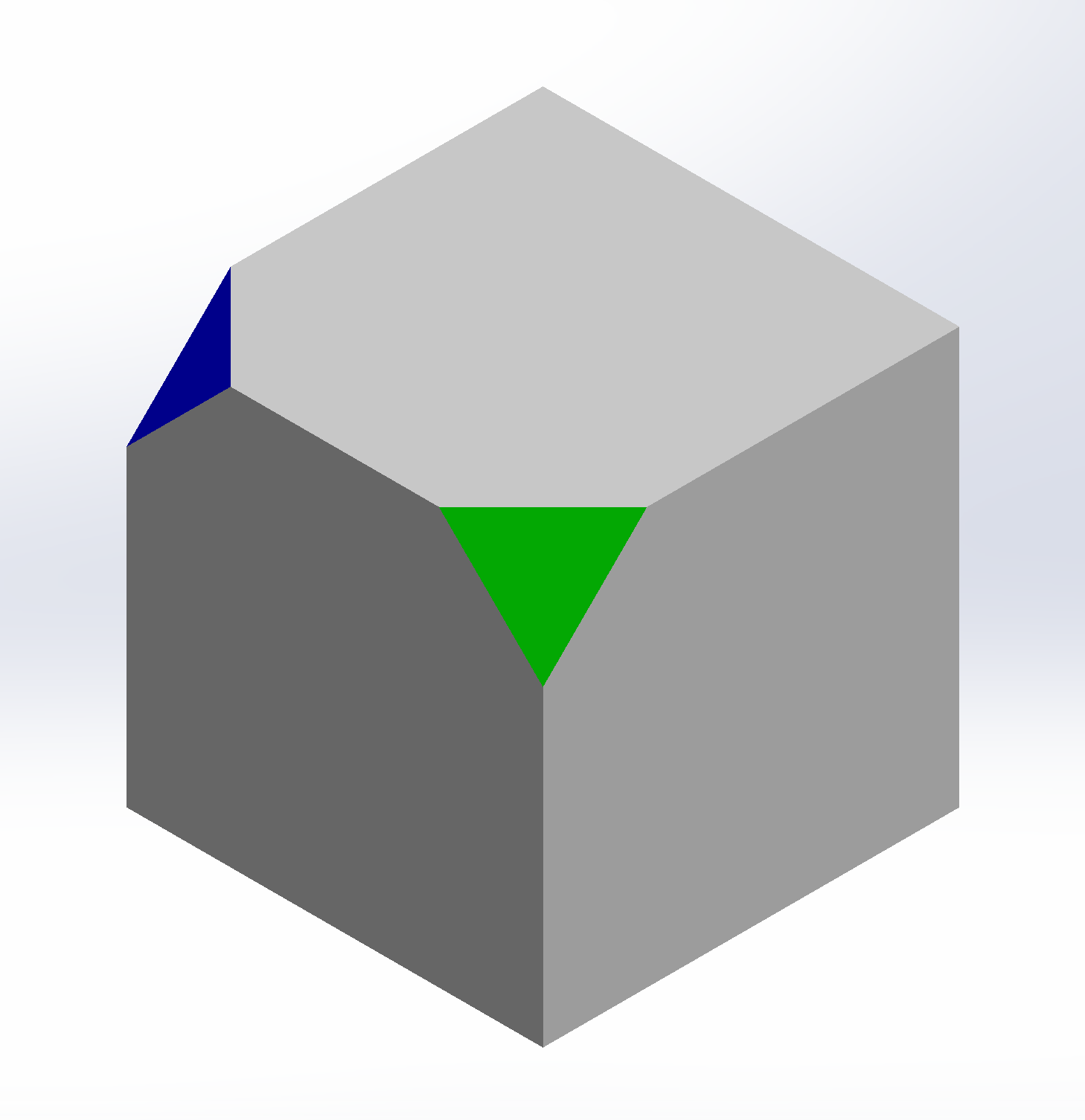
Using the left or right arrow key, click three times
Using the up or down arrow key, click once
Make the view
If you want a view of the other side… reverse above steps to bring it back to the original view of the part that is oriented more towards landscape (that you started with
Use the shift-arrow key twice to spin the part 180° around the vertical screen axis
Using the left or right arrow key, click three times in the direction you want
Using the up or down arrow key, click once
Make the view
That is what we used to do for some parts back in the day. Now the cube has more areas to pick on that make that kind of an older way of doing things for me.
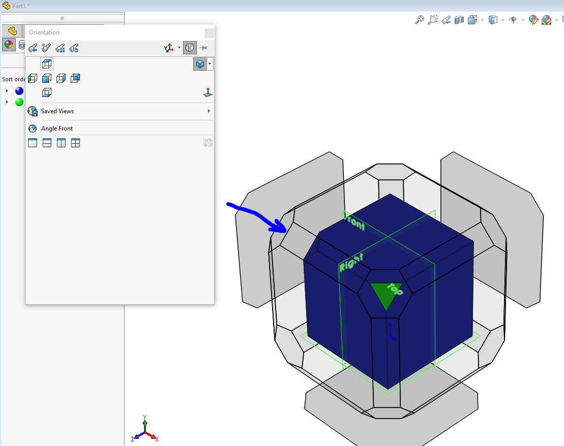
Yeah, I get it… old habits die hard; I never use that cube because it’s cumbersome, but the cube almost gets me to the above way with only one down arrow click to go!click
I like Onshapes and Inventors view cubes, I wish SolidWorks would replace the lower left triad with something similar. The SolidWorks spacebar dynamic view selector cube is a mixed bag. Its actually really good except on really big assemblies its sluggish and slightly disorienting with its zoom out in perspective mode behavior.
What about Dimetric and Trimetric Views? Is there a definition for the various non-normal views? I remember in Solidworks R14, you could specify a view by entering the angles relative to the World Coordinate System.