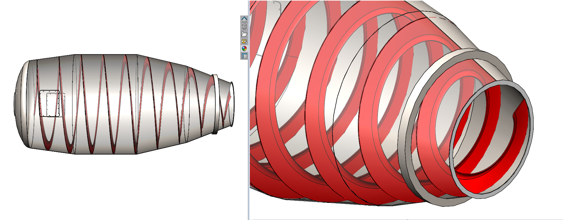
In a past life, i was actually a drum engineer for a mixer manufacturer, but I never actually was able to use solidworks in my designs there. So i guess this was fun to see how I would’ve accomplished the task years ago.
First I insert a new part, and just mate the origin of that part to the origin of my assembly. (similar to an in-place mate)
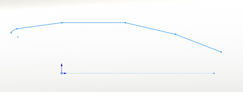
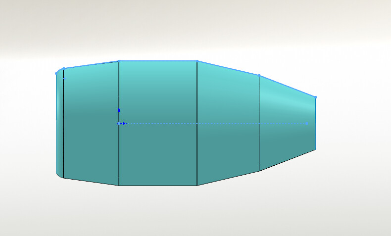
I create a sketch using the inside surfaces of each shell to generate a revolve profile. The sketch will need to meet at the apparent intersections of each transition, so I recommend starting your straight line on each profile, then using the “merge” relation to bring them together.
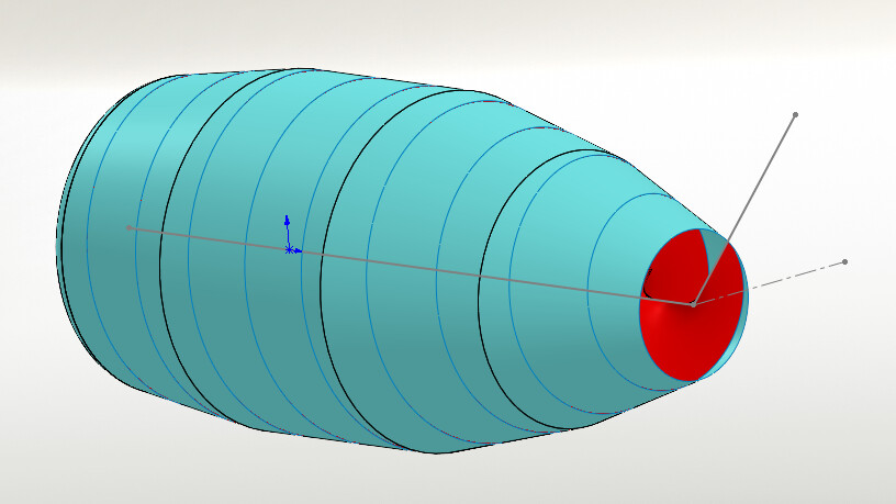
Once revolved, i have a singular surface to use as a trimmer for the helical path I’ll create next.
I created a plane using the circular profile at the discharge end as my reference.
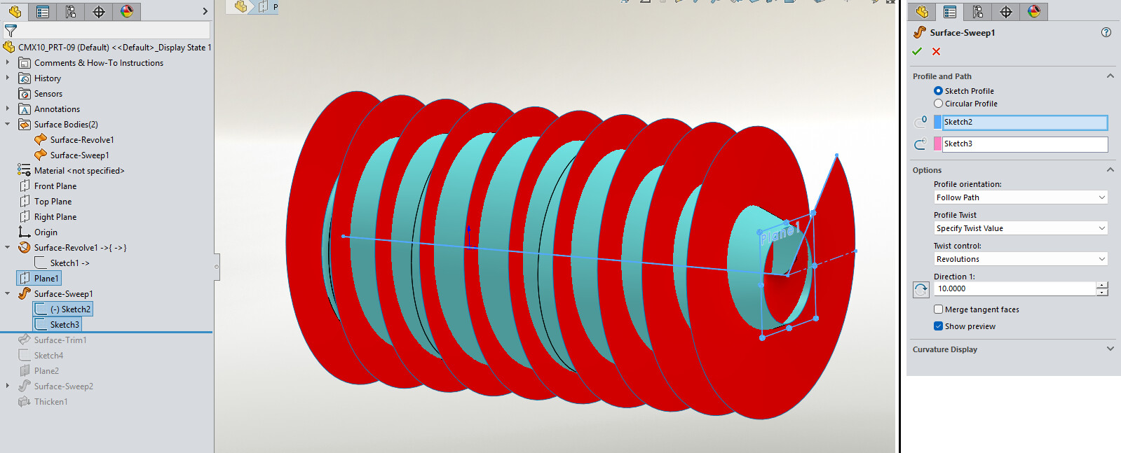
Then, I create two lines. One line on the aforementioned plane. One line that runs the length of the drum on the “front” plane.
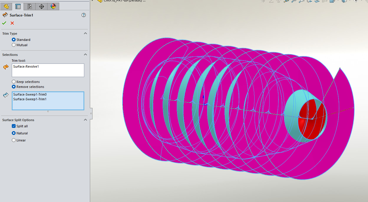
Using the ‘surface sweep’ I can select those two sketches and use the options seen here:
Next i trim the exterior of the sweep using the original surface as the trimmer.
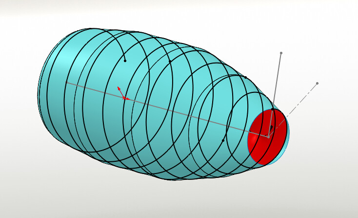
Start a 3D sketch and select the helical curve created by the trim
This sketch will become the “path” used for your surface revolve.
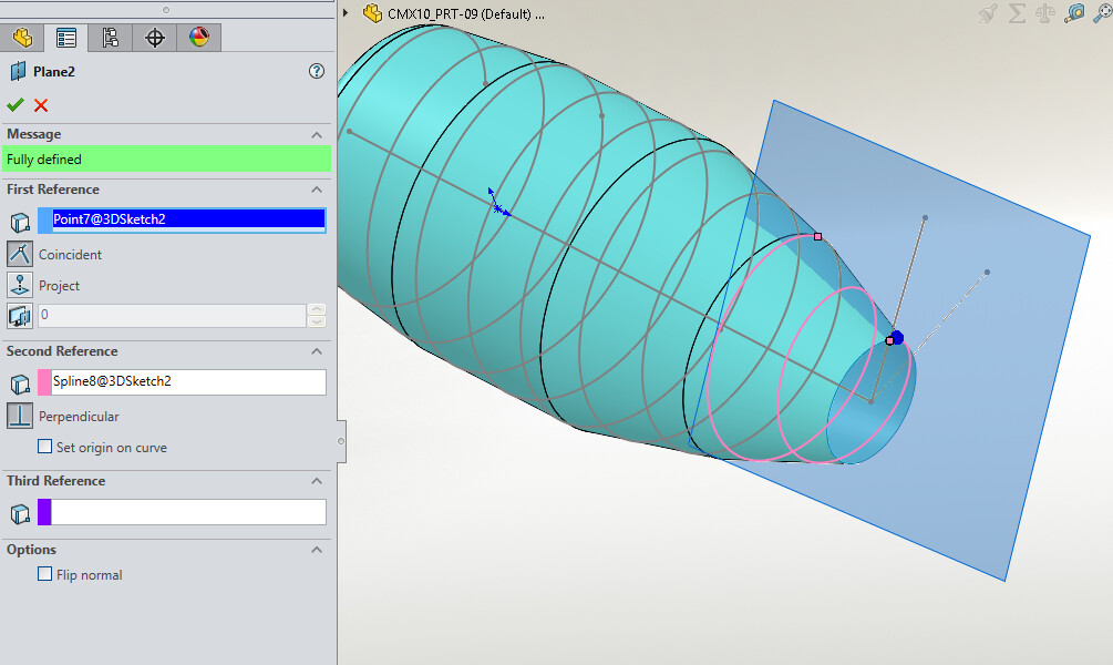
Create a plane and select the end point of the 3D sketch, and the curve as your two inputs. That will place a plane pependicular to your curve.
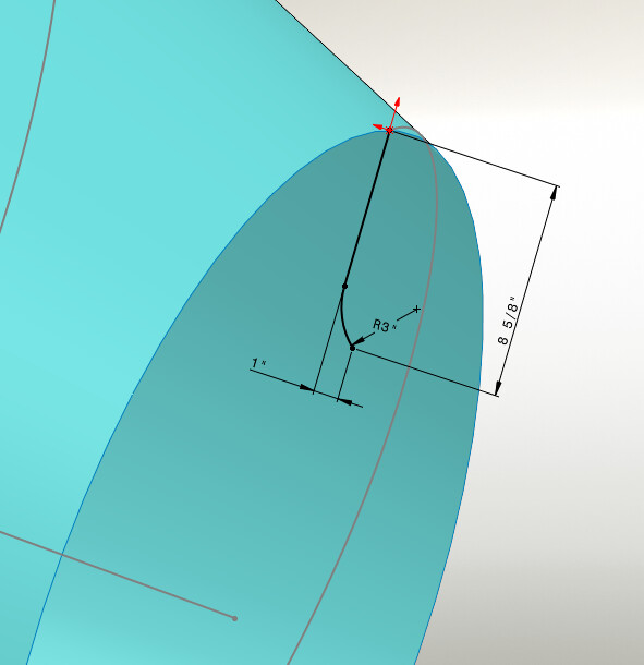
On this plane I start a sketch and create the profile for my “flight”. Our flights had a curve at the end, so my sketch includes this feature.
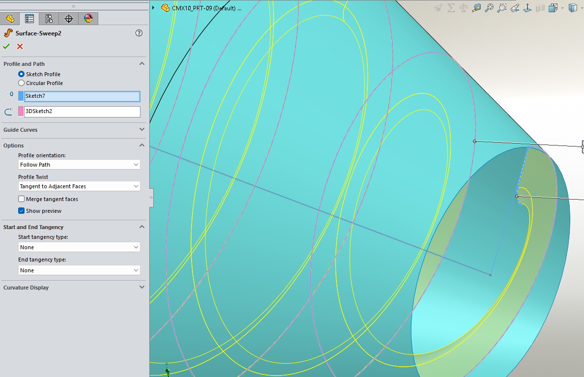
Next, execute a surface-sweep. Set the options as shown:
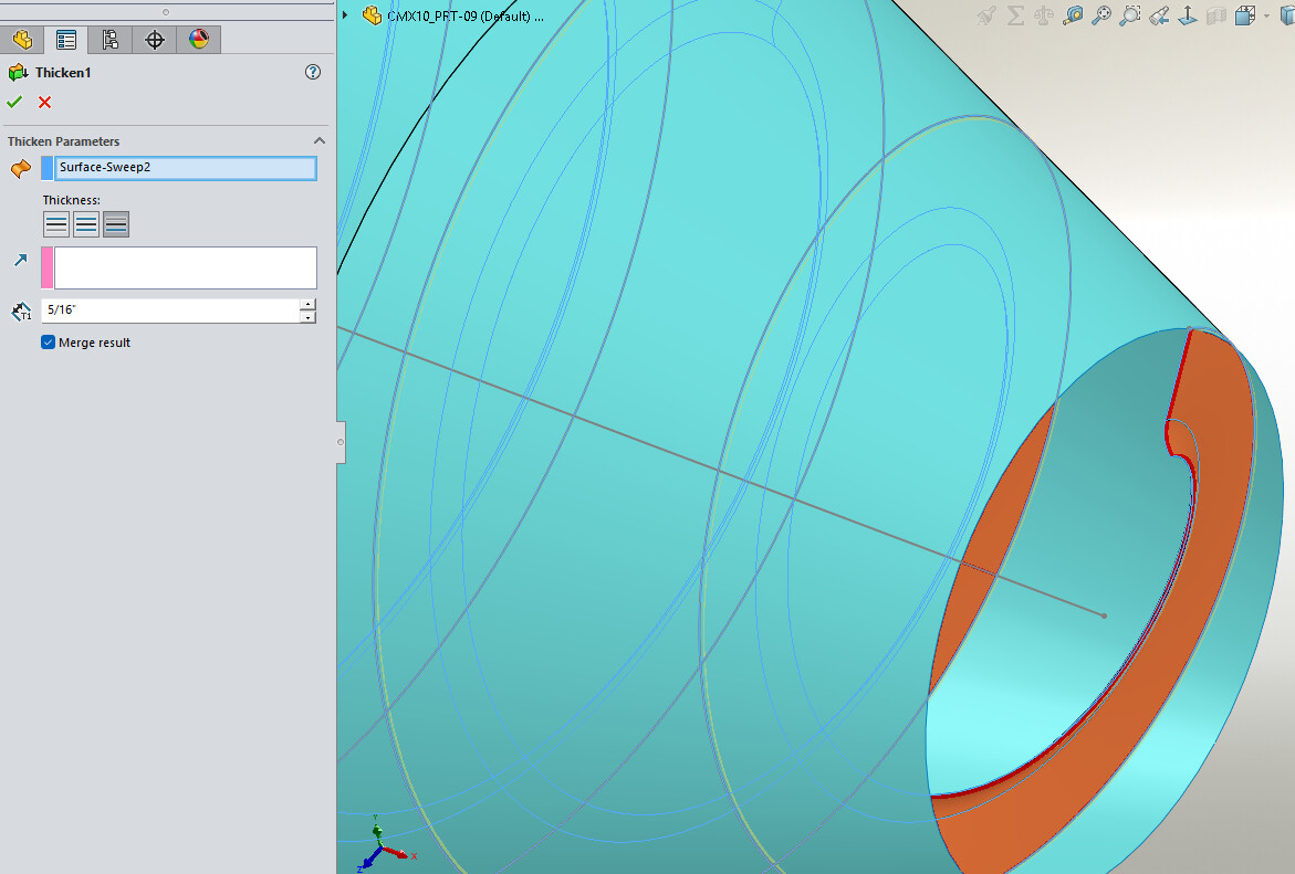
Finally, thicken the surface, the thickness of your plate. I used 5/16".
Technically, if you were actually going to manufacture these, this profile would be split into many peices. Those peices would overlap eachother on one end, so that when they were pulled into place during welding, they could just weld them together front and back.
Cheers,
Tyler