We’ve been hacking it with lines and sketch points “attached” to the edge but if the model is changed and the line or point becomes detached it’s easily missed and since the dimension is attached to the line/point it is not dangling so doesn’t change color. We were used to automatic snap points on these edges that allowed dimensions to be easily placed.
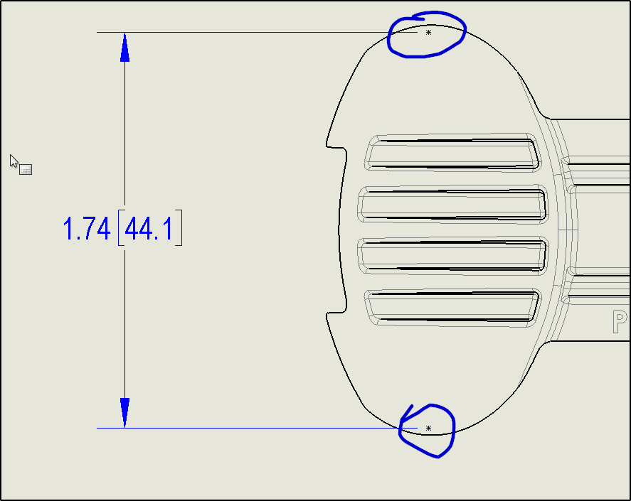
How am I supposed to place this dimension without adding sketch elements on the drawing view?
I don’t work with splines much, but can you put horizontal construction lines in the model sketch and make them tangent to the spline, show the sketch in the drawing view, dimension to it, then hide the sketch? (When you do that the dimensions may disappear; right-click on the sketch in the tree and select “Show dimensions” if it does.)
Thank you for the suggestions, however if I understand correctly we’re fixing the problem in the model instead of the drawing. This causes some problems:
the sketch planes are seldom in plane with drawing views and often the geometry in the finished part does not follow the sketch.
I seldom use splines in my sketches, all lines and arcs, the non-primitive surfaces are results of drafting and fillets in many cases. Other times the faces are results of lofts or sweeps. Maybe I shouldn’t have said spline, I’m not sure what to call it other than the projection edge of a non-primitive surface?
Sometimes other people work on the drawing than who did the model and for them to go back into the model and start adding a bunch of planes and sketches sometimes lead to a mess.
These parts are often dimensioned to in the drawings of upper level assemblies where the projection is different than it would be in the piece part drawing so now we have more planes and sketches that we hope happen to be at the correct angle for the drawing view. Now with PDM we often wouldn’t be able to edit the part when doing an upper level drawing as the part is likely in a Released state.
As I read this I cussed myself for not finding how to do such an obvious task, especially since I’d already seen that because I remember the terminology.
Then I read on and cussed you for teasing me as I realized I remembered the term from Solid Edge where dimensioning to a SILHOUETTE POINT was a simple part of daily life. I thank you for explaining perfectly the process I am trying to do. It’s just that the process is only available in the CAD system we mistakenly left.
Why does it feel like I’m dimensioning to a 3D object when I’m in a Solidworks drawing? In solid edge the elements to which the annotations connected to were on one plane, already projected.
Often features like that are made with sketches that have some construction geometry. Centerline connected to spline points. Sometimes you can dimension to actual feature sketches.
If there are no appropriate feature sketches, then, yes, your method with the sketch elements is the method I use.
You have to know what’s the purpose of the dimension. Is it a real driving dim, inspection, reference… Etc.
Another way to hide the construction lines is to stick them on a dedicated layer and then hide / unhide the layer as required. Dims will remain visible if not on that layer.
I don’t work with this and use pretty much the same method as you, but if I were to work with these and wanted to “avoid” the issue you described, I’d try having feature sketches dimension shown. Pretty sure the change done at the part level never “loses” it’s reference unlike the sketch point would in the drawing. When they are indeed lost in the feature sketch level, it is generally when the geometry is being modified. In those cases, generally speaking of course, the draftsman/engineer/technician then reattaches the elements in the feature sketch, so that the errors in the sketches disappear.
I shouldn’t have used the “spline” word in my first post, that’s my mistake. There’s no splines in any sketch on this part. The sketch for the revolve feature that makes the base of this solid is normal to the drawing view. In other cases the finished geometry doesn’t match the base sketches after drafts and radii are applied.
It seems like dimensioning to the sketches in the model is the most popular response, but I struggle to comprehend that. I try to model for a robust and stable model, I’m not thinking, “How can I sketch this so that I can dimension the part in the drawing?”
Dimension in the model and use Import Model Items in the drawing always works for me, especially for the sorts of dimensions that would be flaky when applied in the drawing environment.
What kind of stuff are you modeling? I must be doing it all wrong! The sketches I make in a model are 90% useless in a drawing. Didn’t we move away from making 2D drawings and move to making 3D models and placing dimensions to geometry a couple decades ago?
I’m guessing dave creates the required dimensions through a 3D sketch or simply by creating reference dimensions, and then he has these dimensions uploaded from the model by using import model items.
I think you’re seeing this the wrong way. It’s basically the same as doing the dimensions inside the drawing, except you do it on your model instead and then import them, because the model tends to fail less then 2D generated geometry in a drawing.
Ok! Thank you for explaining that, you’re spot on, I seeing it wrong. The training of “look how cool SW is” showed using the sketches that made the part used in the drawing so just as you mentioned, that’s how I was thinking of it. I never thought of adding sketches at the end of the feature tree after the model is done for the sole purpose of using them in the drawing.
So many people are doing the drawing dimensions and attached annotations/callouts in the model so the drawing works better?
Technically, I shouldn’t have posted the screen shot in public domain. I was throwing together a generic model earlier that replicates the behavior but Solidworks “had to close.” Of course doing scratch work I hadn’t saved yet, then I had to go to a meeting and after that I didn’t start it again. But since you asked I’ll try to make a model and drawing to share.