I am reverse engineering some parts with complex shapes and odd angles. I thought I was doing pretty good, but once they all started stacking up together it was a mess.
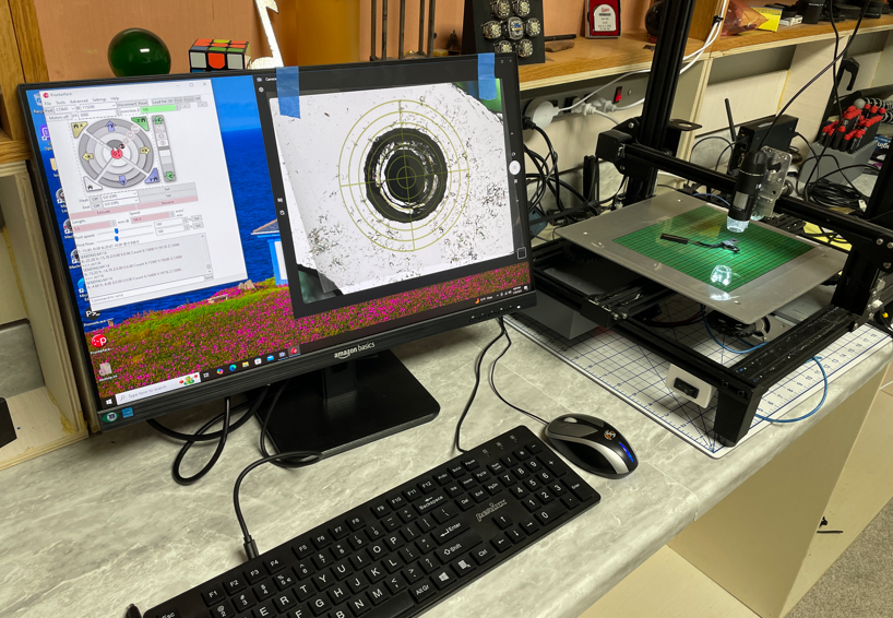
I decided to take a retired 3d printer, remove the head and replace it with a magnifying camera.
image.png
I printed a reticle to place on the monitor. I drive the printer and get the coordinates through pronterface.
image.png
I’ve only measured a couple of parts so far, but the results are better than expected. It is a bit cumbersome, but way more accurate than I can get with hand tools.
I just take a photo of the part, with ruler. Insert into sketch and sketch on top.
Also used mill with digital readout. Get coordinate with edge finder. Plot it in AutoCAD.
I think you are over estimating the elegance of this project.
I am simply using the gantry of the 3d printer to (somewhat) accurately position the camera, and report the coordinates.
I already have all of the parts in cad, but they needed to be more accurate than what I had been able to accomplish.
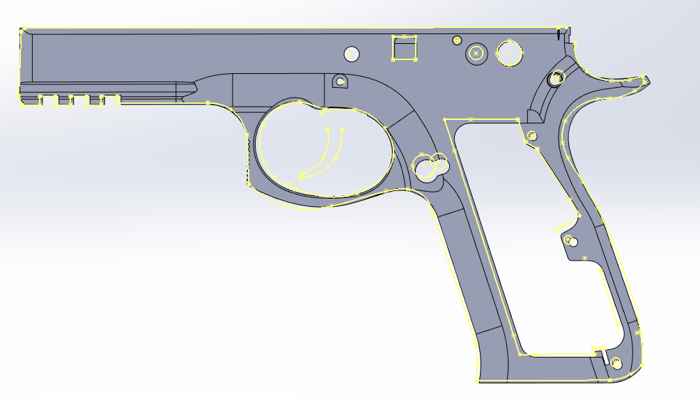
Step 1: Layout the points to be measured
image.png
The frame is the part with the most features, and is where all of the other parts come together. I had over 100 points before it was all said and done.
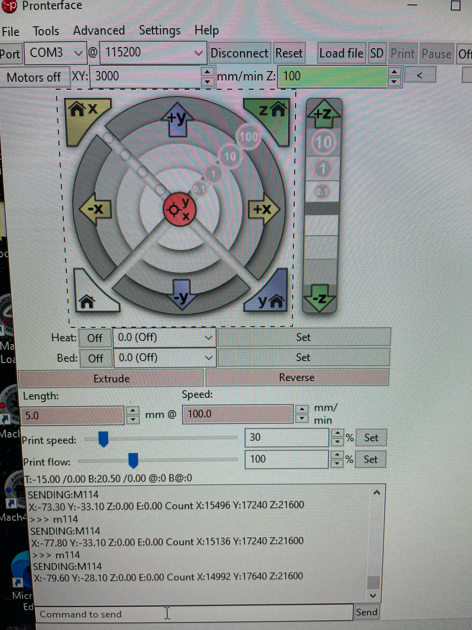
I’m using software for boards with Marlin firmware to both position the gantry, and report the X Y position.
image.png
I jog the gantry until the crosshair is aligned with the feature I want to measure, send the command to the printer to get the coordinates, and enter those numbers in a spreadsheet.
image.png
I printed the reticle on clear transparency film and taped it to the monitor. Not a very sophisticated solution, but it works. The output of the USB camera is being displayed through the default microsoft app.
image.png
The only code involved is this macro from Artem. I use that to import the point cloud into a sketch in Solidworks.
Once I had the points imported, I added enough geometry to make sense of it all.
The next step is to overlay this with the model and started correcting things that are off.
This project became a priority again in December. I spent a bunch of time and a little bit of money trying to make the CR-10 frame work as a CMM. When it was all said and done, I abandoned this approach. Maybe it was the cheap GRBL board; maybe it was the plastic wheels for bearings and belts for drive, but once it was all up and running the repeatability wasn’t there.
At that point I realized I had a proper CNC router in the garage. It started life as a OneFinity CNC router. Last year I put Masso steppers on it and replaced the controller with a UCCNC board and software. I also found an overly tool that put a reticle on the screen so I didn’t have to have a plastic one taped to the monitor.
The final step was to find a way to easily record the X,Y coordinates. The controller software has probing functions built in, along with the ability to add macros. Unfortunately by this point in the project I was way behind schedule, and I wasn’t making any progress on automating the process, so I used ShareX to take screenshots at each position. Worst case I would enter all of the values manually.
I decided to see if AI could be of any help processing the screen grabs. I asked ChatGPT for help. It said “I don’t do OCR, but once you’ve done all of the hard work, I will be happy to put it in a CSV for you.” I tried the same thing with CoPilot and it said "Here’s your CSV. Is there anything else I can help you with?
The end product was a success. I measured the accuracy to be 0.005" / 0.1mm and was able to refine all of the small parts to the point that everything matched up in the assembly.