Nice to meet you guys, first post here. Hope it’s in the right place.
I have been modeling some Gyroids recently, but I can’t improve it anymore, would appreciate some help. Below I described the steps to achieve the best result I got until now, so it might be easier to spot where the flaw/improvement is (Also am attaching some files here - SW2021 Version):
image.png
Create a cube and convert it to 3DSketch (with origin in the center)
Draw Arcs and constrain them on the planes of the cube (have also done it with Fit Spline and made them tangent, but the result was not neat)
Delete Body (Original Cube used for the first 3DSketch)
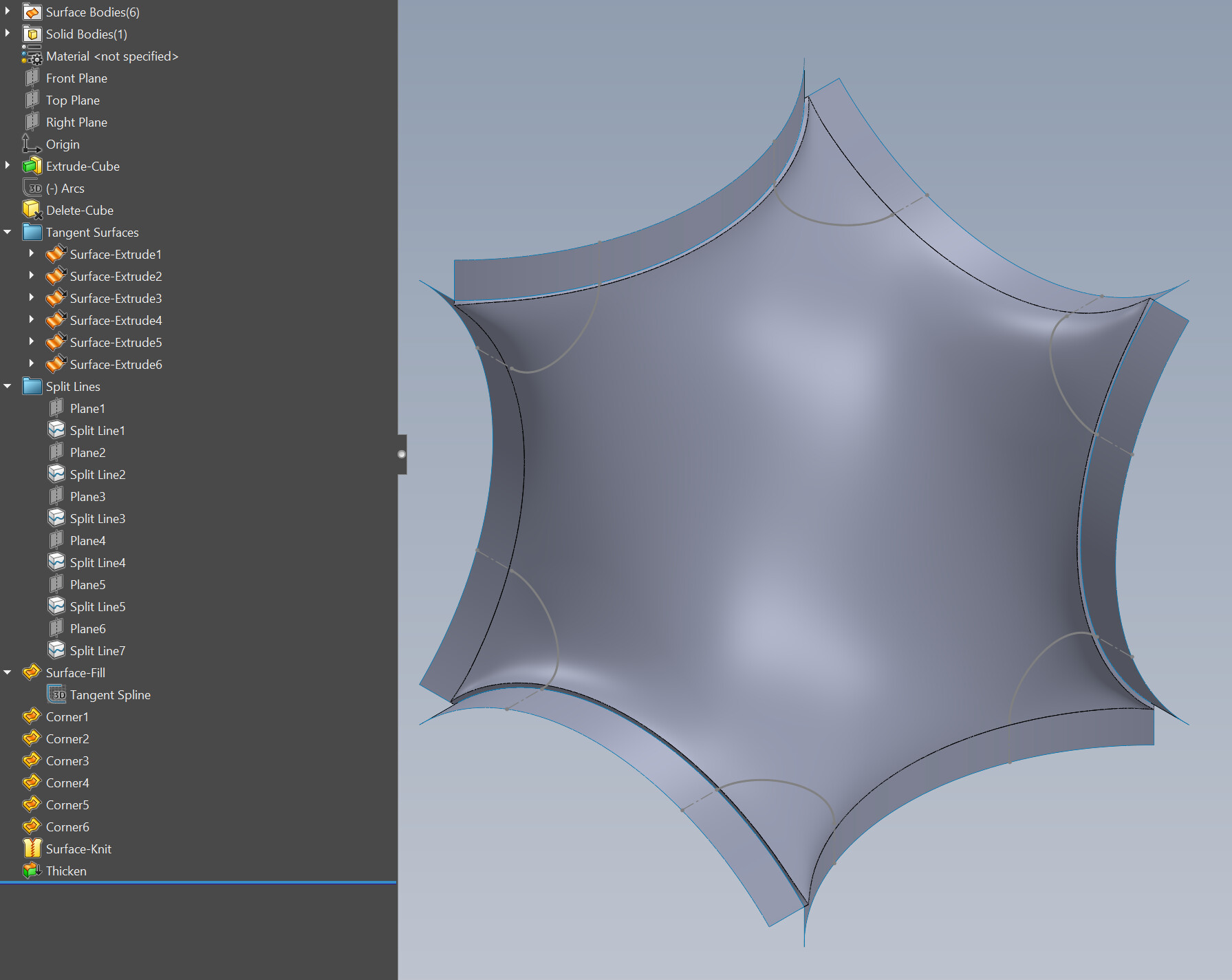
Convert Entities (Arcs) in different 3DSketches and Extrude Surfaces with them
Create 6 Planes parallels to the originals and create Split Lines where they intersect the Surfaces (so it is possible to select de edges without the corners)
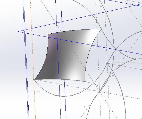
Create another 3DSketch, convert the Split Lines and draw tangent Splines connecting the lines (reset their handles) [1]
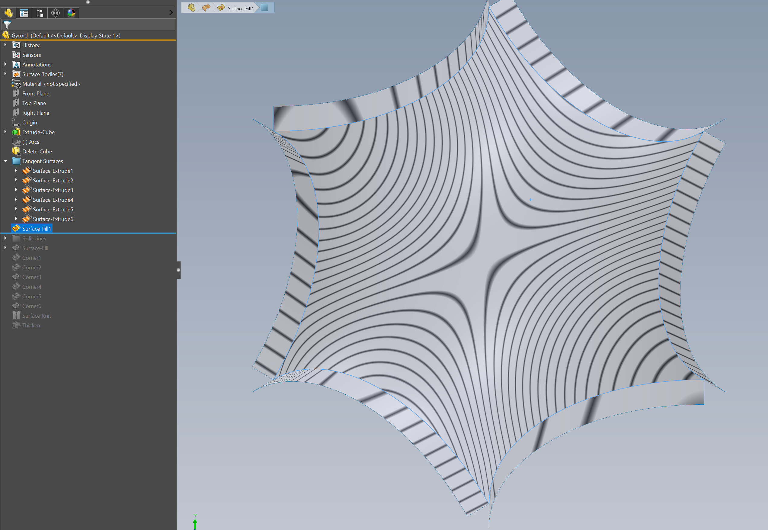
Fill Surface with edge tangency and the 3DSketch of Splines [2]
6 Fill Surfaces with edge tangency in the corners [3]
Knit
Thicken
[1] Guess a point of improvement would be not using splines at all, what can be done here? I tried using Curve Through Reference Points, but the result was worse.
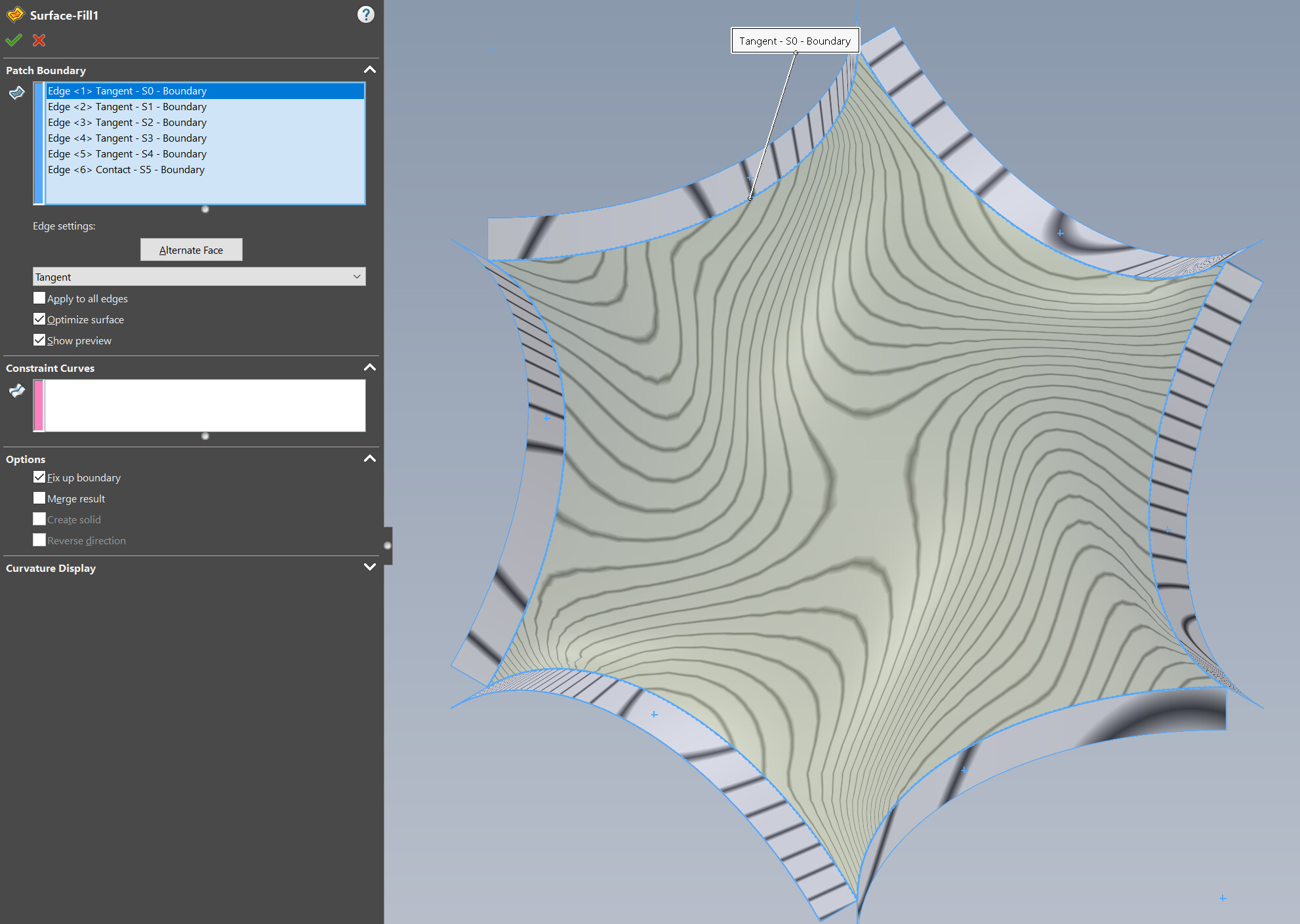
[2] Also tried Curvature on settings and uncheck Optimize surface. But I have some problems trying to compare different results, how would you suggest doing it?
[3] Tried different distances for those parallels planes (changing the Split Line position), but the result was kind of the same independent of those Filled Surfaces sizes
Later is where the trouble comes:
Create an Assembly and start connecting the surfaces (using planes as reference Mates).
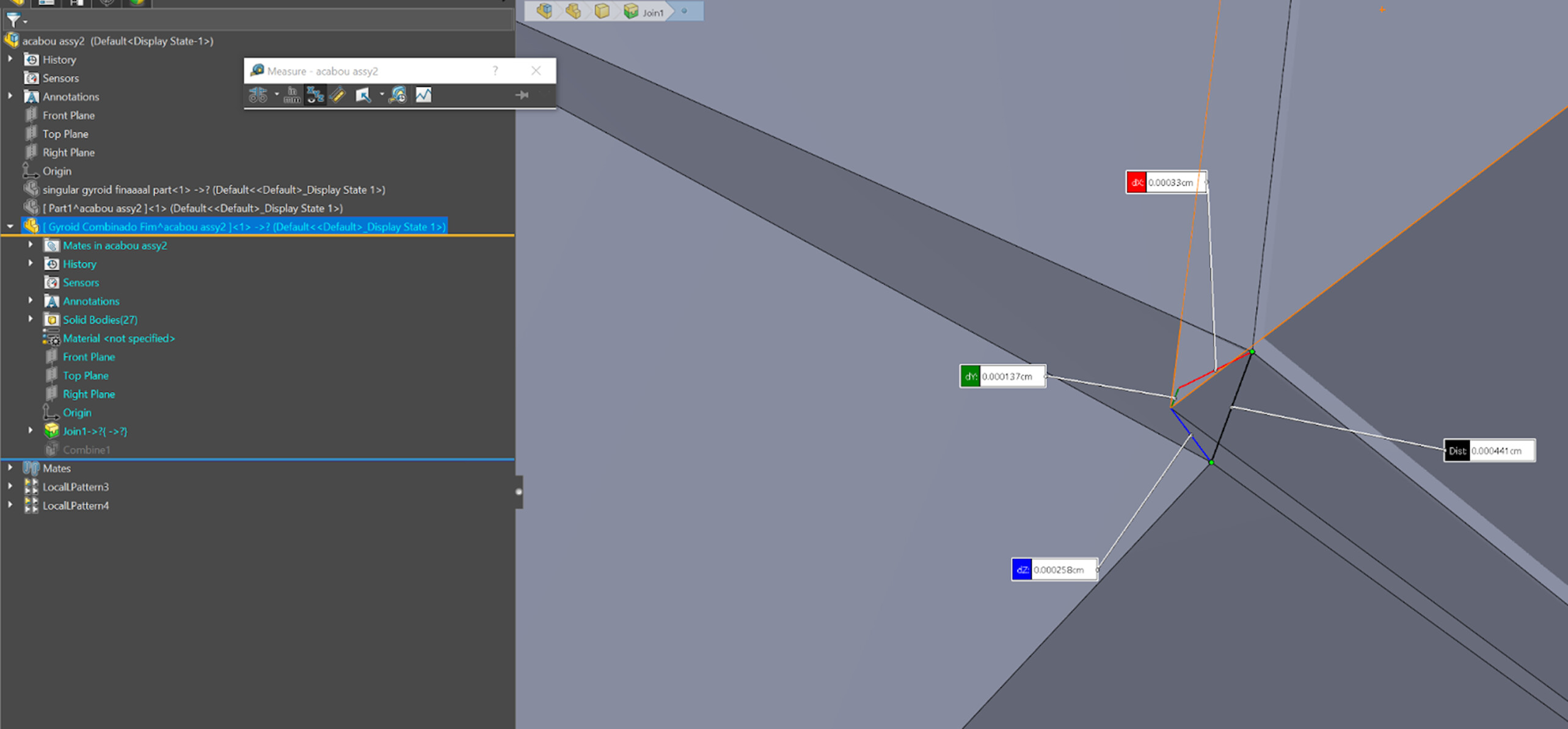
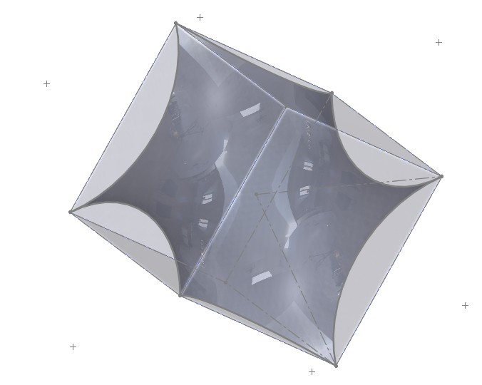
Somehow the tangency on the Edges are not really tangent and it is notable the singularity on the corners (suppressing the Thicken helps to analyse better).
After creating a “cell” assembling 8 surfaces, create a New Part inside the assembly and Join it all together in one part.
Combine to merge all the bodies.
*Somehow the corners get all knitted and neat here and I have no idea why. (Did not use “Force surface contact” in Join Feature - when I used it the waiting time was so long that I gave up.)
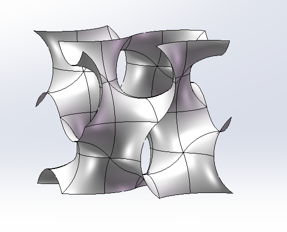
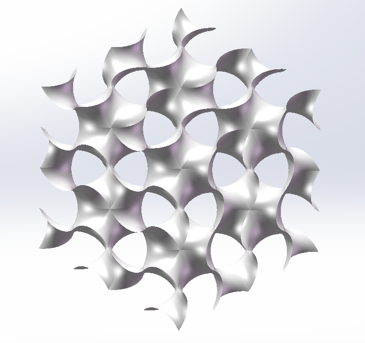
After the unexpected result, pattern it twice to create a large volume with it.
*Notice that the corner will not be properly merging, but repeating the previous steps (Create New Part → Join → Combine) will fix it again. ??? lol
→ Does anyone know why the Combine feature is knitting the corners? This is the result I wanted but it should be already merged when connecting the bodies in the Assembly. Also, how can I make the geometry perfectly tangent, like a gyroid should be? Guess the main problem is in the Filled Surfaces in the corners
→ Any suggestions on the steps are welcome.
I exported many STL files and checked them in Materialise Magics, did not require any fixing for the structure (which was great ), but it is noticeable the lack of smoothness in the joints.
Pictures in SW and Magics with/without Combine Feature
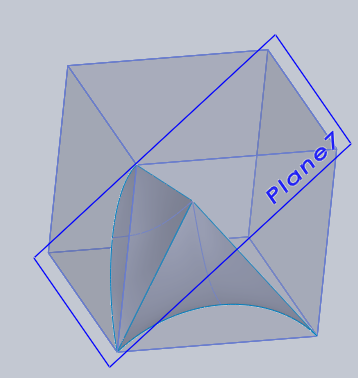
In this file I only used splines on the “Tangent Spline (3DSketch)” . It wans’t possible to make a 3D tangent arc in both Split Lines for the contour; Since the split lines are in 3D the connector should bend to fit in both. Maybe there’s a way to fit tangent arcs, without using those split lines…
About the Assembly, I was doing this method before when working with lattice. Somehow the software handles better heavy files in assembly mode (can also lightweight them) and it is also better to rotate the part to see it. Doing everything in one part file was taking a lot of processing time and patience. lol
You can actually create a surface using all the sketch on cube face using Fill surface while using the internal sketch as constraint curve.
image.png
Seem like it is not that easy to get the surface to transition smoothly at the joint…
image.png
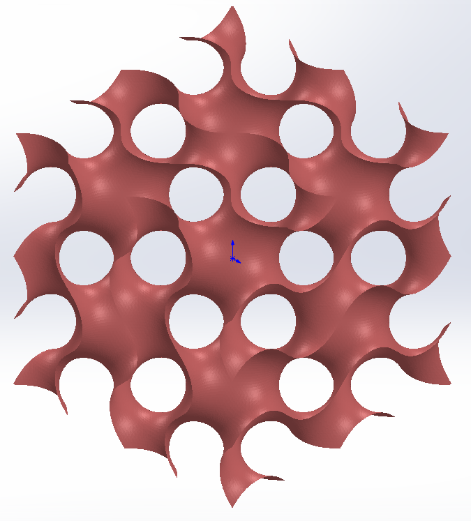
As i spent more time than i expected, in the end i sort of give up and brute force my way through
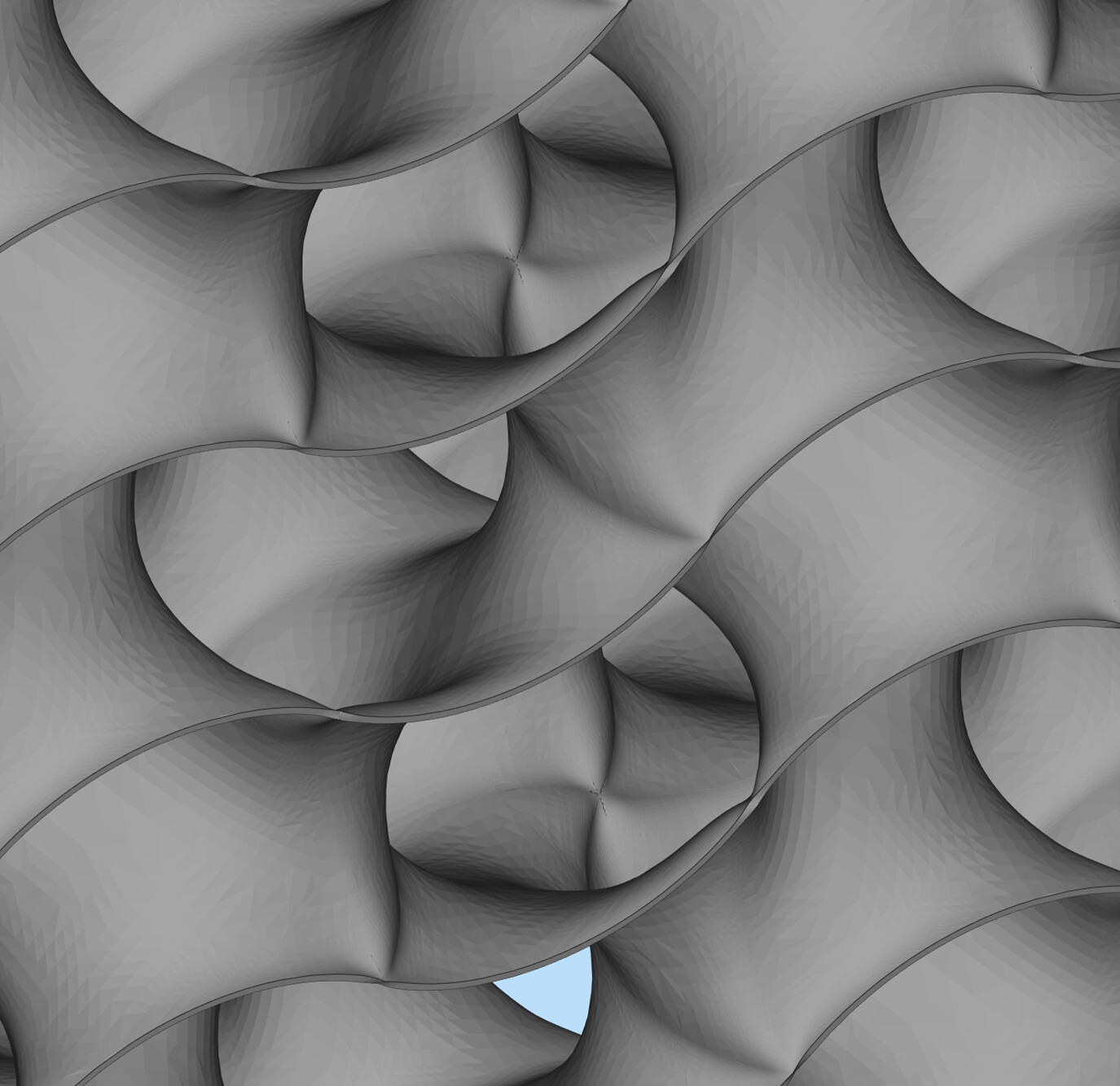
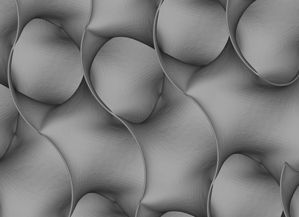
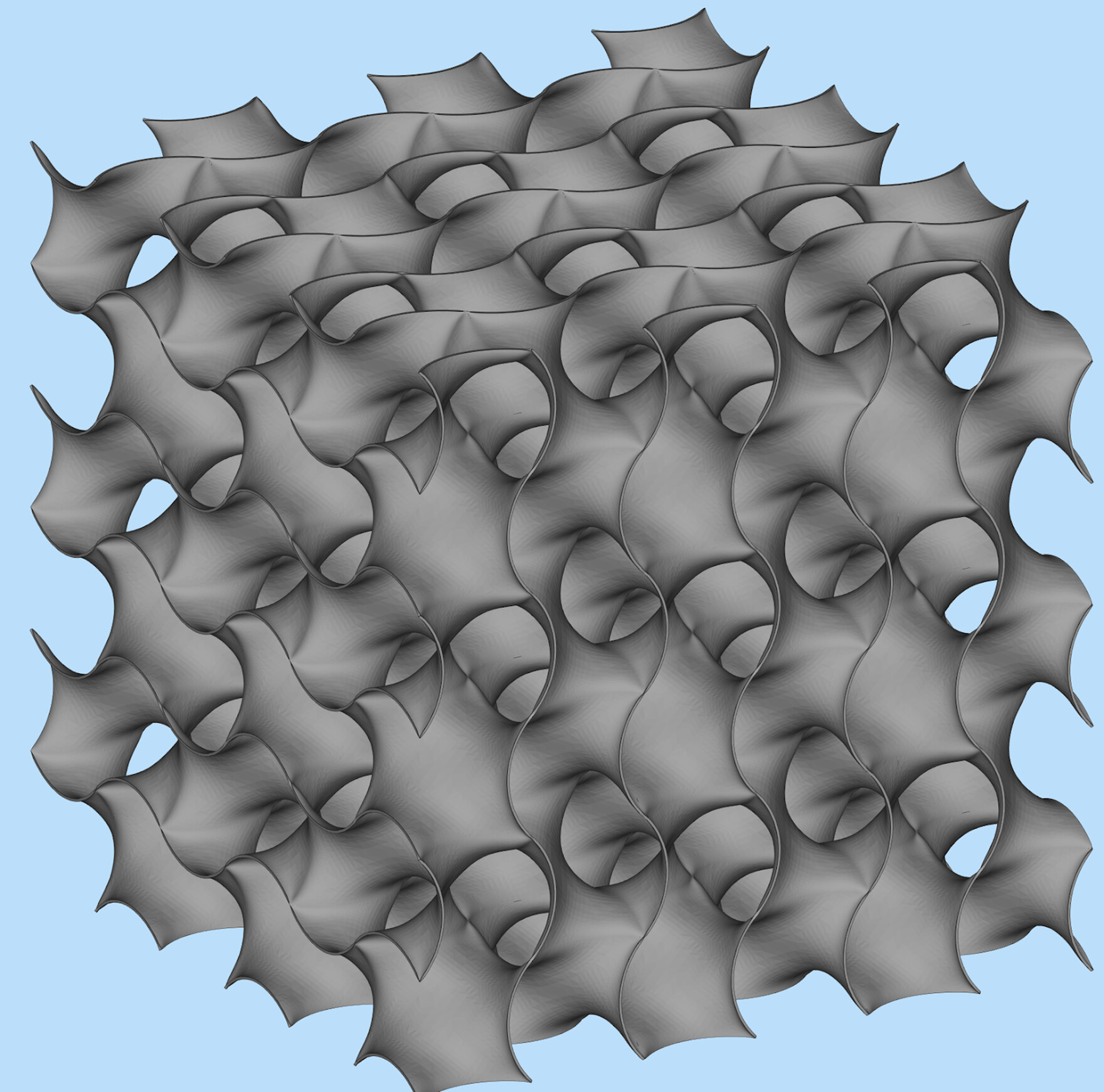
What i did is just generate the gyroid as isosurface in matlab and export as STL in 5min
image.png
image.png
image.png
SW hung up 3-4 times and my machine blue screened once working on this.
You can simplify things with symmetry. The main shape of the part is essentially the same shape 12 times.
I tried a few things:
each surface is made of 12 symmetrical bits, so I mirrored the 1st one and then circular patterned the rest.
image.png
image.png
image.png
I made a single fill feature straight from your arcs
You can also do it with a Boundary if you draw lines from the center of the cube to the corners, and use those lines as Dir1 and use the arcs as a closed loop in Dir2. It may not have the tangency properties you’re looking for, but it’s an interesting way to make a shape.
So I played with this a bit and the way I approached it was to break the first unit down even further. You end up with two pieces that you can then make the entire thing out of that are simple lofts with four edges.
I started playing with this trying to figure out the complex surface using planes and. As I kept making the surface smaller and smaller units I ran into a spot where the surface only comprised of the four edges so I lofted that surface. I then realized that I should be able to have a mirror of that to complete the arc…then realized that was the only two pieces I needed.
Part one
image.png
End essentially it’s mirror
Part two
image.png
I then created the first step assembly by using the two pieces in every other position.
image.png
Then made a cell from the previous assy
Then a block of cells
I’m sure it’s not a perfect Gyroid because I just faked in the arcs but looks to me like you could make the arcs in the initial pieces anything you wanted as long as the end points were in the right place and tangent to the mating part or cell.
matt, I’m sorry, I might have saved some files with high resolutions in image quality, maybe it wont crash if you lower it. Usually I drop to the minimum when assembling then increase it after, so I can evaluate better.
About your methods, very interesting the first and the third one. Never thought it would be possible to do this with boundary, I will check it. lol
MJuric, this is a nice approach. but SolidWorks only keep contact constraint with sketches, so the surface will lack smoothness in the edges. This method works well with NURBS
******************************
Some zebra results:
This is just with contact constraints (just need the arc sketch to do, and lacks tangency when assembled)
G1 Conect.PNG
It is not possible to make all the edges tangent or curvature continuous, but it is possible to create leaving one with contact constraint. The shape is not good though:
G2 tangent.PNG
G3 tangent.PNG
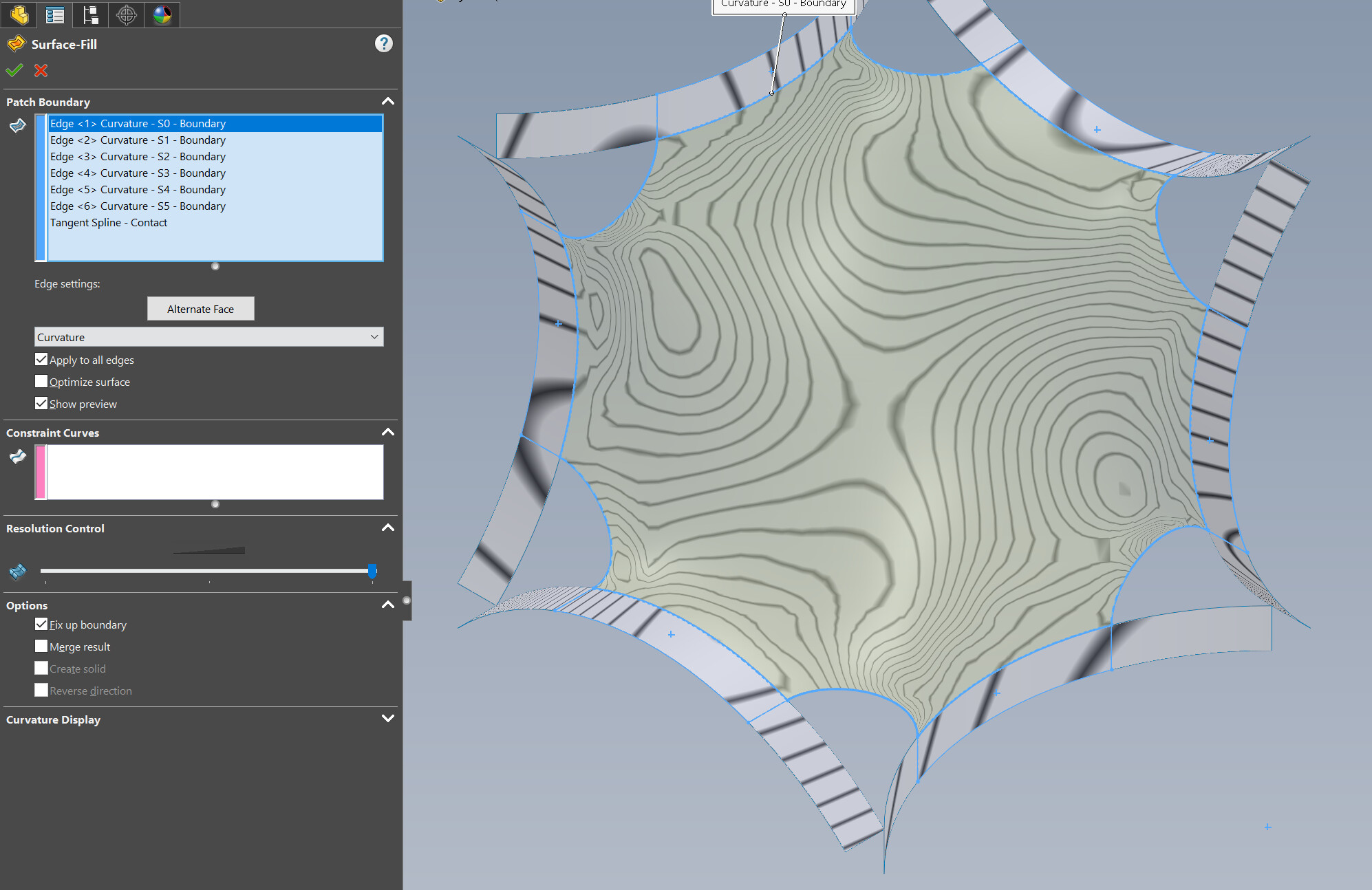
With curvature and one contact:
G4 Curvature.PNG
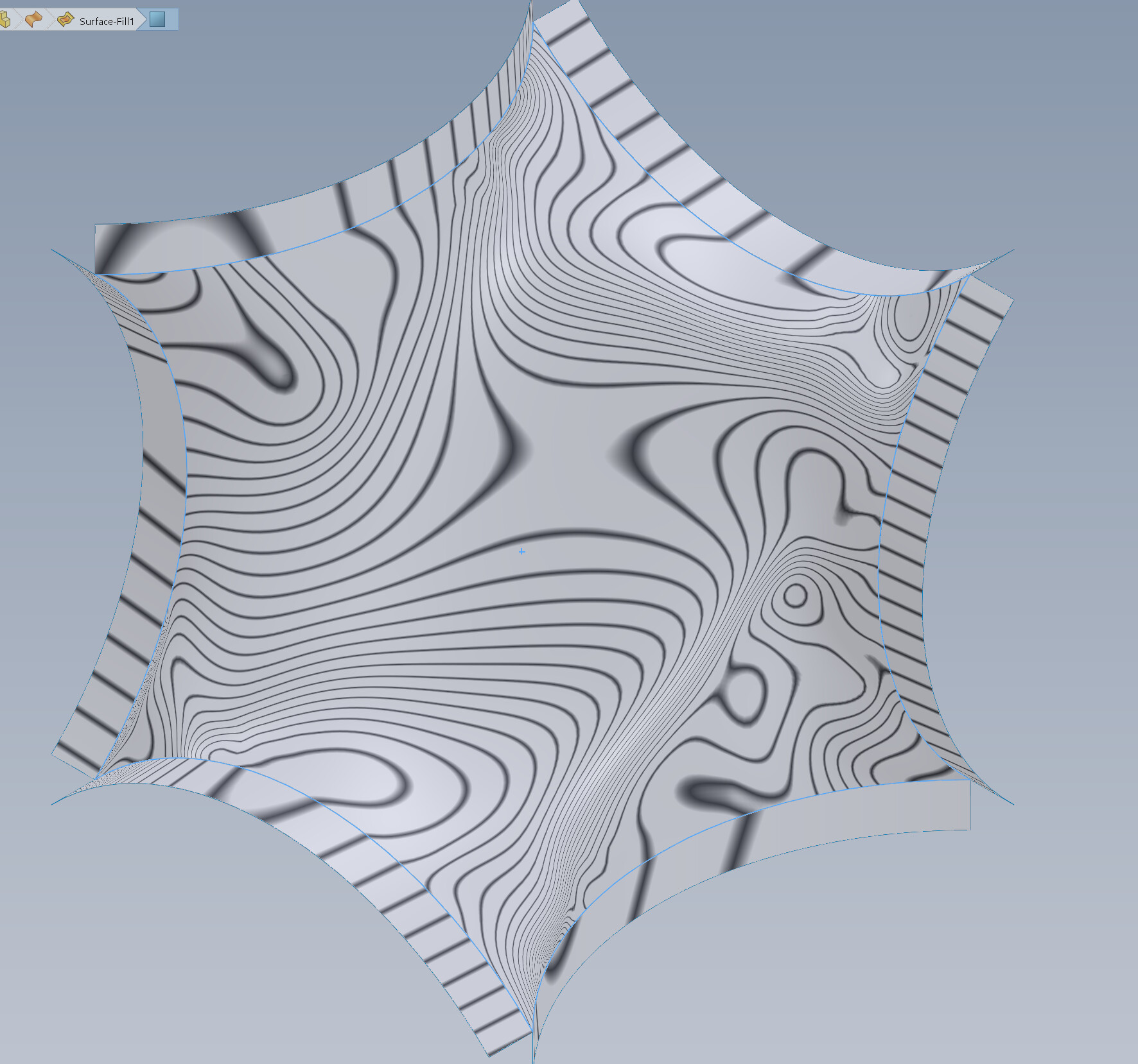
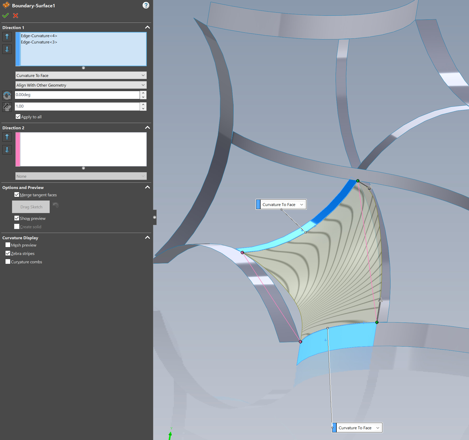
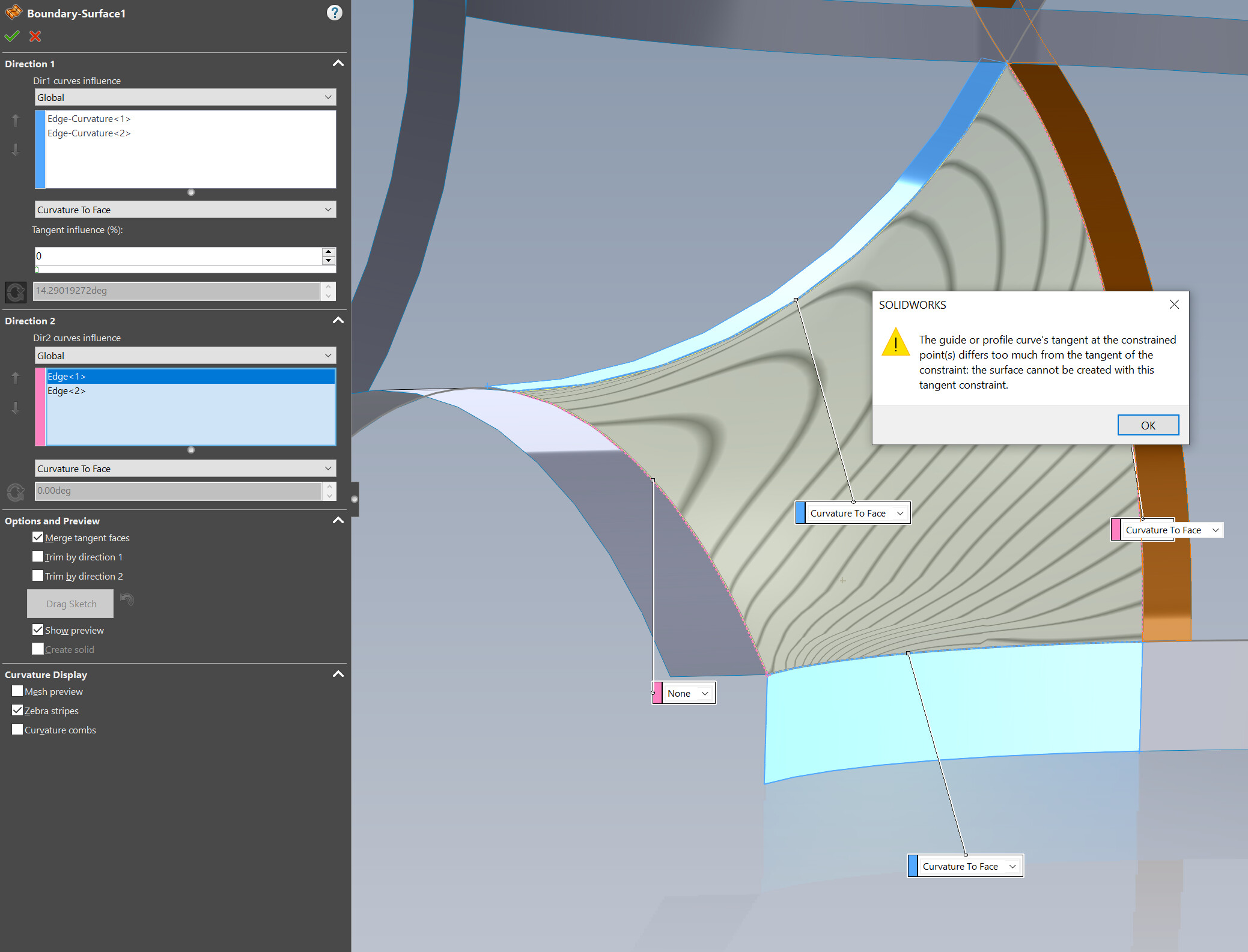
Here I have tangency constraints in all edges:
With curvature it is not neat
Curvature in every edge:
I think there might be another way to make this contour without splines, so curvature continuous will look better, but I can’t figure another way… have any suggestions?
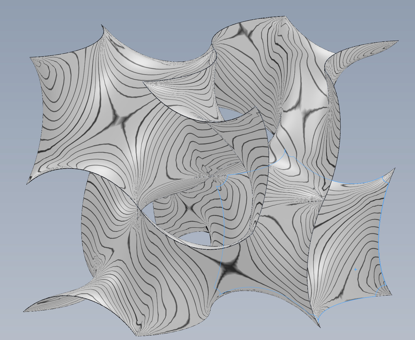
Improving it a little bit. Reduced the Filled Surfaces sizes almost to the minimum and the Thicken to to the maximum.
More than this the Filled Surfaces would start to bend and the Combine in the assembly would result in zero thickness. Also sharing the files:
image.png
image.png Gyroid2Assy.SLDASM (11.9 MB)
Not a surface guy so how does this smoothness effect the model? IE if you had a sphere that was a single surface and then split that sphere into two halves the zebra stripes would not show a continual line on the split version but aren’t both version the same “Smoothness”?
[quote=MJuric post_id=8592 time=1624279910 user_id=57]
Not a surface guy so how does this smoothness effect the model? IE if you had a sphere that was a single surface and then split that sphere into two halves the zebra stripes would not show a continual line on the split version but aren’t both version the same “Smoothness”?
[/quote]
It affects mostly the appearance. A gyroid is just a surface bended in many directions, it doesn’t have any notable joints. Here is a more detailed explanation about curvature continuity:
That type of curvature control can also be important in strength, dynamics, fluid dynamics, cams, and all sorts of motion. Accelerating with a sharp in the path will lead to a shock, and the smoother it is, the more you can distribute the shock, making parts last longer, or for less turbulence in flow, or removing a stress concentration in a structure.
I’m aware of the effect of an actual lack of smoothness in the real world.
What I was wondering is what is the difference in SW when you have two surfaces vs one surface both of which are essentially the same smoothness.
When I drew my Gyroid, unless SW models it incorrectly, the smoothness of what I drew should be the same as that of a single surface. However if I look at the Zebra stripes it shows a “Break” at the joint areas.
In other words from what I can tell my model would be as smooth if I manufactured it as a single surface because all the joint areas are tangent…again unless SW breaks that because it can’t create the single surface properly.
The settings that you use in a feature do not always really control the outcome. That’s why we have the evaluation tools, especially the Deviation Analysis so we can tell numerically how far off from tangent a connection between faces really is. There is (almost) always a little tolerance between complex surfaces.
It’s great to model the smallest possible surface, and then mirror/pattern bodies to get the full shape you need, but it’s the connections between the bodies that causes the problem. So you avoid the problem by making larger bodies with fewer connections, and trying to make fool-proof connections. It’s one of the hair-pulling circular conundrums in SW surfacing. The easy methods give you bad models, and the methods that give you good models are (seemingly) impossible.
This is why we sometimes make bad connections and then patch them.
Ok, so what you’re telling me is that SW creates surfaces that aren’t really what they are supposed to be
I don’t work with surfaces often and 99.9% of the time it’s to fix an imported part where I’m just trying to get it to be a solid so I really don’t care much about how it “smooth” it is.
That being said, what is the purpose of making a software that doesn’t make surfaces as one would expect? I can see having options to manipulate the surface to make it so it is not as one would expect, but I would think the default would be “Ok the surface should start and end perfectly normal”, which would mean mating joints would be what you sketched not “Well something we decided it should be”.
Probably going into the weeds here but how does SW “Decide”, “Nahhh, I’m not making this one right/tangent…oh but that one I am.”.
Edit to add: BTW this is information that I wish I never had…now things like this will bother me when in the past I would have blissfully ignorantly have gone on my way thinking "Welp, those two surfaces are tangent…well because that’s the way I drew them