I have a model that I’ve worked on for several weeks, on and off, that suddenly developed some sort of display glitch. Any ideas?
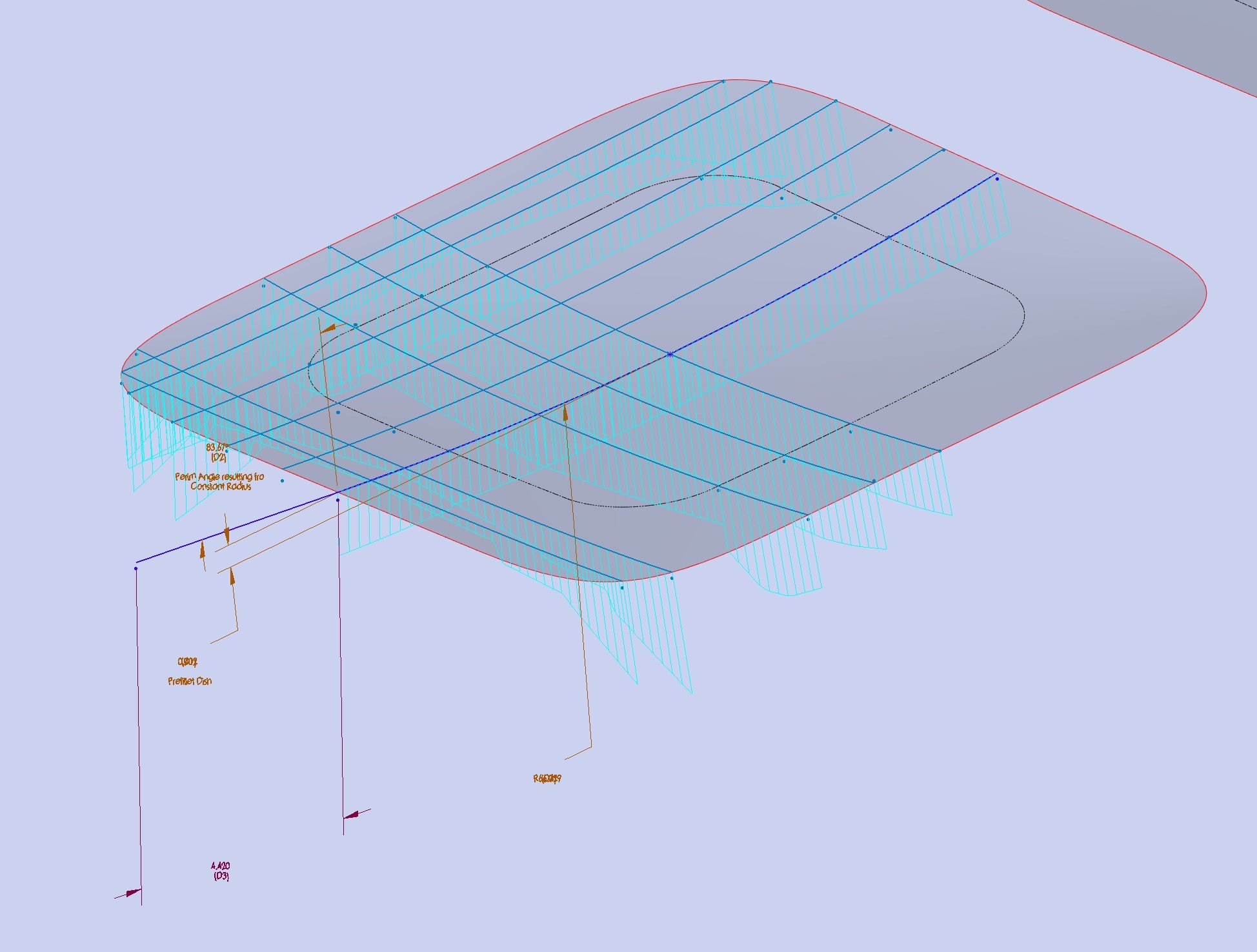
As you can see in this screen capture, vertices don’t align with the end points of sketch entities, and the text associated with dimensions is jumbled.
It was modeled in Swx2020, but I see the same issue in 2024. I see the same behavior on different machines. I see the same behavior whether or not I activate “enhanced graphics performance”. Same with using Software OpenGL.
I see the same behavior if I roll back to the top of the tree. Ctrl+Q doesn’t fix anything. Save-as doesn’t fix anything. Other files work fine, as do older backups of this file.
Any ideas?
Thanks!
Ryan
Wow that’s classic “SW” bugginess if ever i’ve seen it! Sorry i can’t offer much of a suggestion but have you tried importing the part into another part to try and “refresh” it? Perhaps that may be worth a try.
Open offending part.
Create New Part.
Insert Part → Select offending part
Click “Break link t original part”
Click the Tick Box at top of dialog to complete.
Heard back from my Var (GoEngineer) and they had a solution! It appears just activating a standard view might be enough to resolve. Here is the full procedure they gave me:
The issue you are seeing is called “Z-clipping” this occurs when the “bounding box” – invisible box used to control how large a window SolidWorks must generate, does not resize properly. (different from the sheet metal bounding box). The “bounding box” is an invisible cube that the SOLIDWORKS® software uses to estimate what region of the graphics area to calculate the graphical display of the model.
The following steps may fix this problem:
- Press the space bar to open the ‘Orientation’ dialog.
- Select and apply a standard view orientation, for example, ‘Isometric’.
- Force rebuild the model (press ‘Ctrl-Q’).
- Save the document.
- Close the document.
- Re-open the document.
Thanks HercalloY! That is a trick that I use to update parts into new templates. Your idea work in this case as well, but I had about 20 configurations in the file, which would need to be manually recreated. In my other reply you’ll see that just activating a standard view was enough to cause solidworks to recalculate the graphics-related bounding box and fix the glitch.
Thanks Glenn Schroeder! None of those did the trick this time. The fix was even easier. Just activating a standard view allowed solidworks to recalculate whatever was “off”.