I make panels.
Most of my part are a set thickness with configured Lengths and Width.
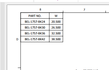
In my drawings, I place general tables manually enter dimension (L and W)
Because its manually entered, I have gotten get caught many times when the part is changed and the drawing is not update.
In the past I’ve tried using Design Tables in a drawing but I find Design Tables very difficult to control.
I have found that the size and location of a design table in the part controls the size and shape of the table in the drawing. VERY DIFFICULT!
Is there a way to have a GENERAL TABLE automatically populate with all the configuration names from a part and read a named dimension (L & W)?
Maybe something I can make a template from?
Why not use a BOM…? You could have your dimensions linked in properties inside your part, and reference those properties within the BOM to display the desired dimensions
image.png
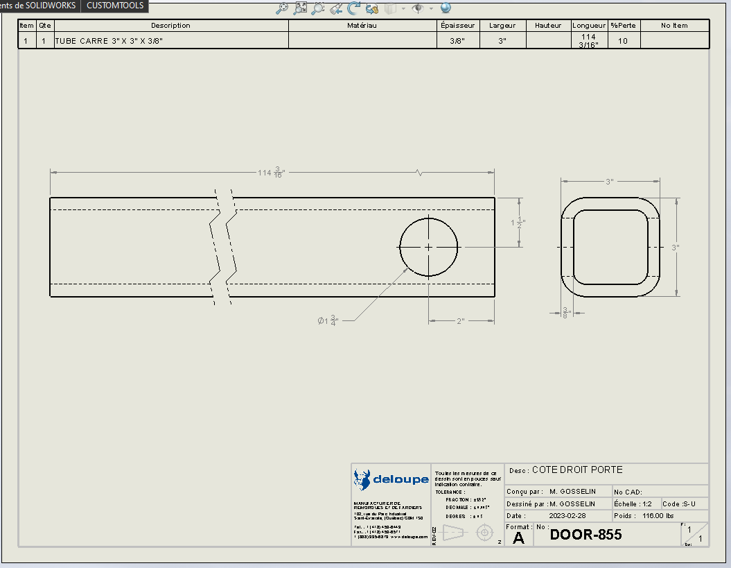
Well, depending on your work set-up, you could use a cut list.
This is a cutlist for our weldments, it is auto-populated by information contained within the weldment profile and the length is driven by the sketch that drives the feature. These are item properties from the part cutlist.
image.png
This is a cutlist for a sheetmetal, the information is contained within the item properties from the part cutlist.
Thanks AlexLachance .Your always a big help…But I’m not quite there yet.
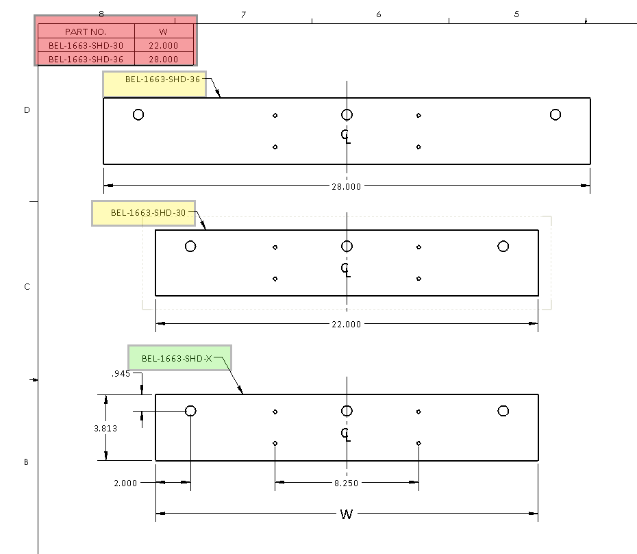
Here is another example of what I currently do.
The GREEN is the part number. This part/view would be the only view in the drawing.
The YELLOW is the configuration names. These are here for reference to show that they are near identical. They would NOT show in the drawing.
The RED is manually entered information.
I would love to be able to drop a table that would pull the configuration name and the 1 variable dimension in automatically.
Even if it were a macro that would need to be re run anytime there is a length change!
Like I said, I’ve tried Design Tables but their size and placement are to unpredictable.
I’ve never tried putting a design table into a drawing before and as you say it is pretty awful.
The way I did it was to create a general table linked to the view, manually populate one column with the part number and then copy and paste the matching configuration length properties for each configuration from the part to the table second column.
“D1@Sketch1@@A@Part3.SLDPRT”
“D1@Sketch1@@B@Part3.SLDPRT”
so on
This at least links the dimensions to the part configuration but if a part number changes…
I can use the solidworks BOM to produce cut-list type descriptions. I dont bother with cut-lists or trying to force sheetmetal components onto these description based BOM’s. I only use dimensional references or bounding box references.
image.png
I should add to, that you can also use design tables and generate your properties that will update as the part changes, however, the caveat is that once you save the table and close it, the property evaluates and the next time you open the design table the evaluated value is in the place where the associated property text once was.
image.png
Therefore, you have to keep a copy of your spreadsheet saved exteranlly that has all of the un-evaluated property text, so you can copy / paste it back into those description cells should you need to make edits to the design table.
Fun.. i know.. but I’ve learned SW is usually just one comprimise merged into another.