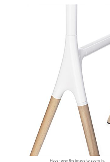
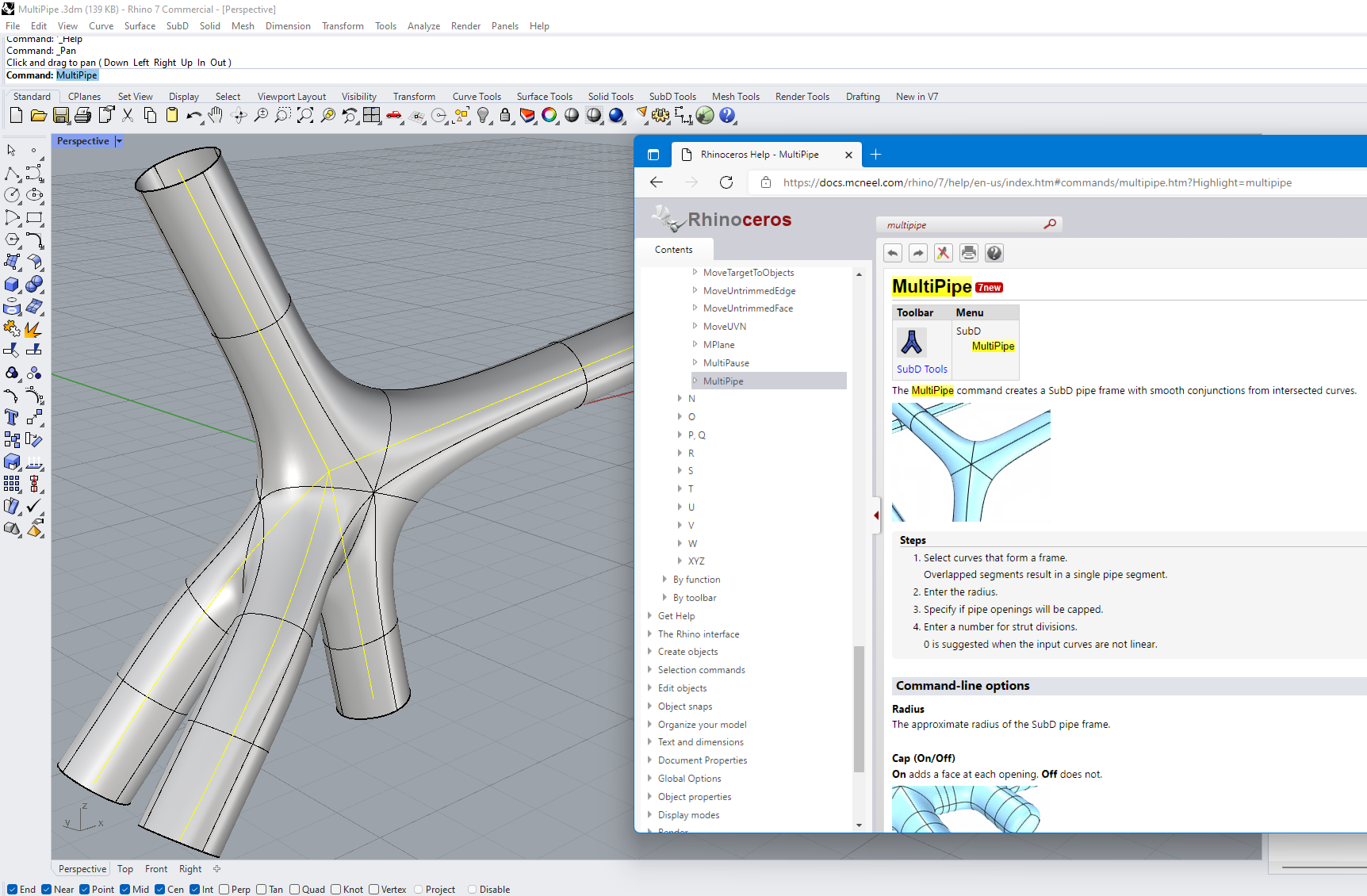
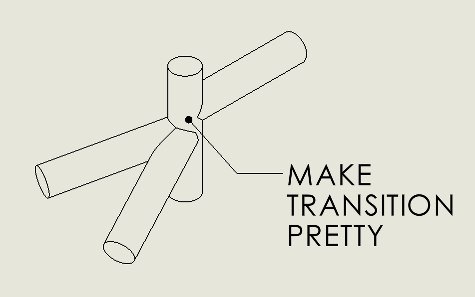
I saw a guy asking for advise about how to this on Reddit:
image.png
This kind of joint is pretty common on carbon road bikes, although they are more likely to use truncated NACA profiles and probably an advanced surfacing software NX/Catia/Alias/whatever (do you know what they use? lol)
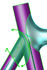
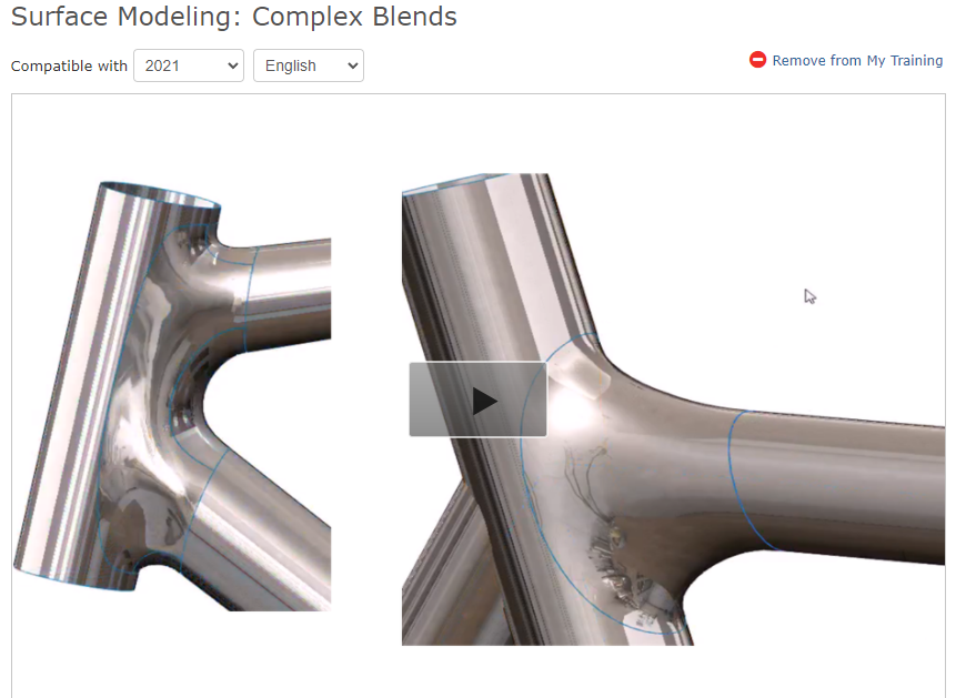
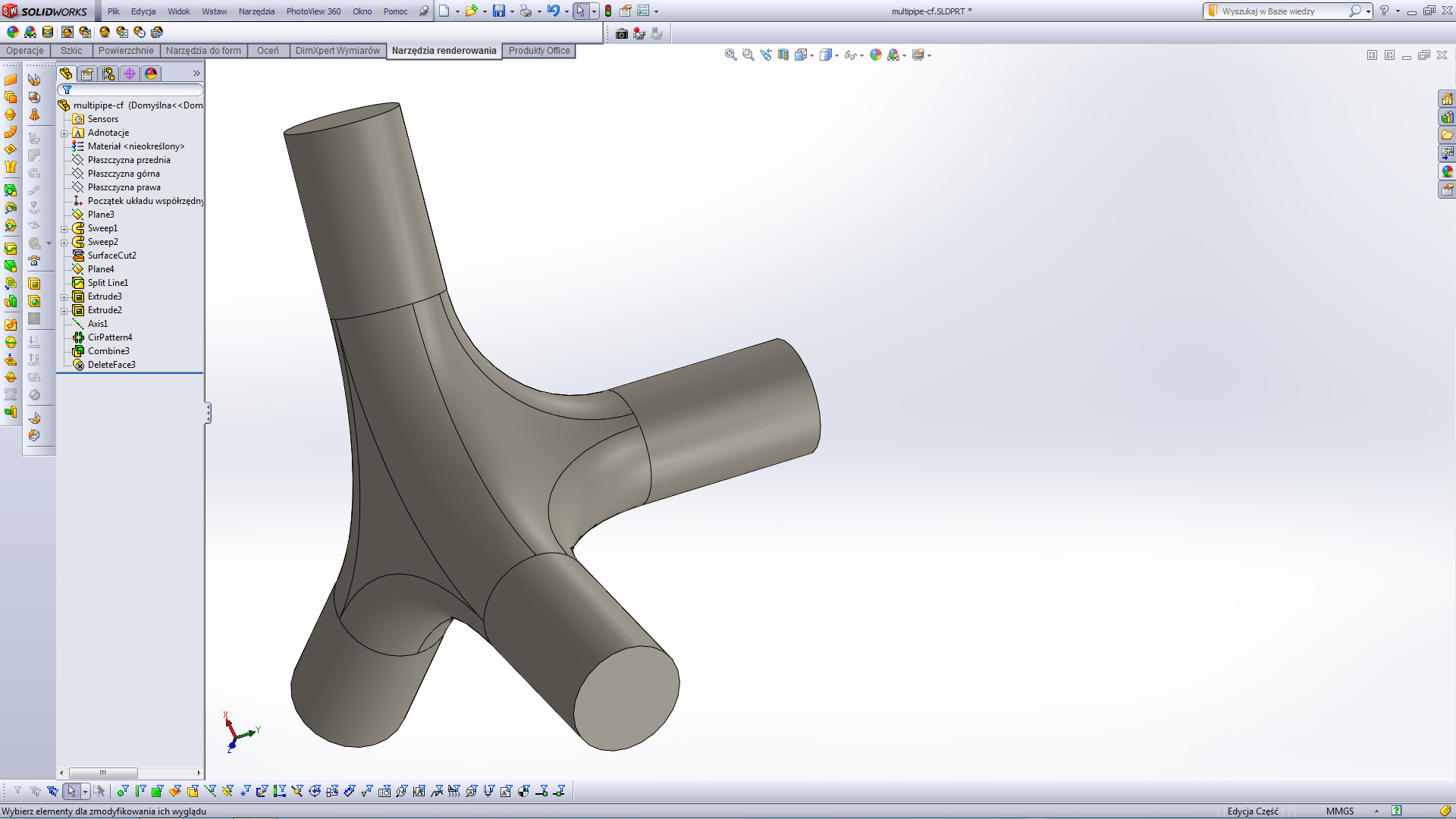
Anyway, I gave it a try using boundary stripes and fill surfaces, everything has a tangency continuity (Yey ):
image.png
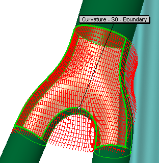
image.png
But making all those Split Lines were a pain. Would be nice to have a subdivide tool on the edges, is there something like it?
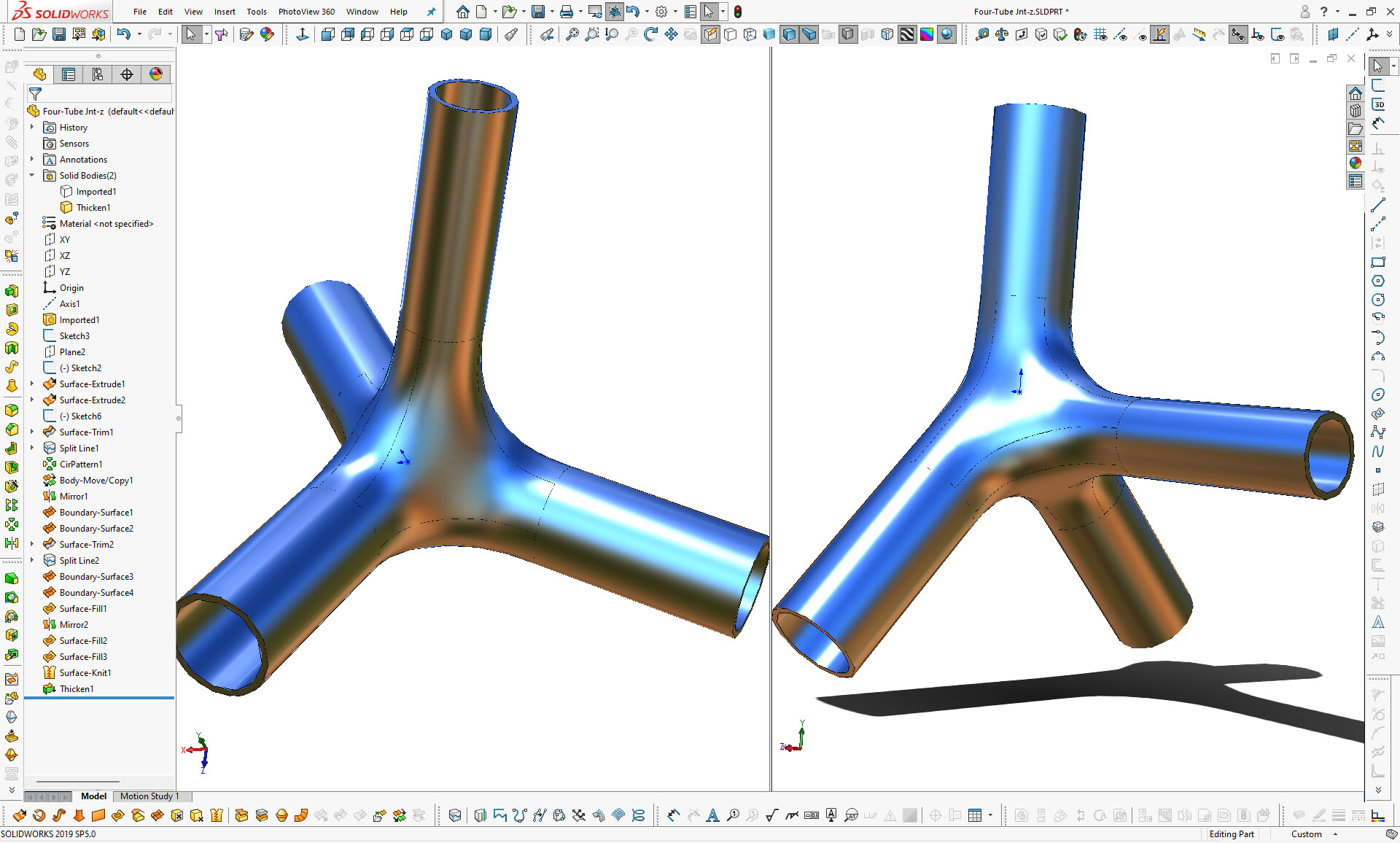
One other way to split it would be with Trim Surface and add Split Entities on the sketch, but it does not feel appropriate to this 3D condition (I mean, having a good precision)
Well, bending a little bit and adding a hole you have the Bottom Bracket area, or adding another tube you have a model with integrated seat post. Not with this round shape tho, just steel bikes use them… but yeah, doesn’t look so much, it just resembled me a Giant TCR SL for some reason. lol
Still, I tried to make a Bottom Bracket joint after this and failed miserably. Doing something like a carbon frame modeling in SW seems a work for masochists hahaha
If you don’t like using the split points in the trim sketch, you could just use the handles in the feature. Maybe constrain them to 3d sketch points. I don’t know of any way to split edges directly. I’ve made several joints like this, and have always used the split points in trim curves. bikeex1104.tif (115 KB)
[quote=matt post_id=13011 time=1632502133 user_id=49]
If you don’t like using the split points in the trim sketch, you could just use the handles in the feature. Maybe constrain them to 3d sketch points. I don’t know of any way to split edges directly. I’ve made several joints like this, and have always used the split points in trim curves.
[/quote]
That’s some nice joints. Have you tried making some in SE?
[quote=MJuric post_id=13008 time=1632498667 user_id=57]
That’s a case where something with more organic capabilities would be the better choice over something like SW.
[/quote]
Using Subdivision looks so nice and smooth, can’t wait to have this in SW lol
It’s very possible in SW… but yeah, it takes time setting up… and yeah, it would have been friggin great if DS would have had the balls to include SubD into SW but they failed all of us.
One of the kewlist new features in Rhino3D is MultiPipe.. it’s exactly what your wanting… I did this in less than a minute in Rhino and ~3min total to transfer into SW. (images)
Do you ever do your surfacing in Rhino and then bring that surface into SolidWorks to finish off the part?
I’ve been considering this as a workflow to get better surfacing designs done.
Not often enough. I just add what I need when I need it when SW can’t and go back to SW.
There are many ID Designers/Companies I’ve worked which use Rhino3D, very common.
It’s worth getting or look at Moi3D.
I posted about this plug in for Solidworks but if this is the kind of work you do, and lord knows NO new surfacing tools have been introduced in over 10 years, then you might want to take a look at X-Nurbs.
As far as SubD modeling goes (and this is staying within the more CAD-Like Software’s)
Your example is so simple that it can be done without using surface tools. We often complicate the task ourselves. Sometimes it’s better to send a soldier on a bicycle with grenades than to send tanks