hi dear members
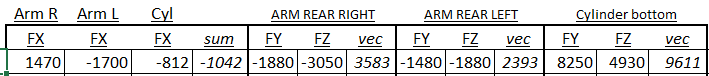
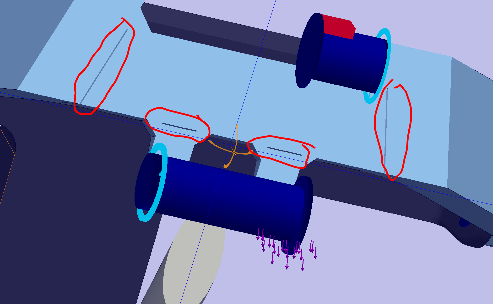
i am trying to understand the behaviour of forces in given product , so i am trying to figuring out how forces found out from results at given image areas.
Thank you
hi dear members
i am trying to understand the behaviour of forces in given product , so i am trying to figuring out how forces found out from results at given image areas.
Thank you
First things first, I ran your analysis and it failed. By that I mean this is an invalid analysis - the stress shown is greater than the yield limit so linear analysis is not going to give you valid results. Second, why does it look like your force is at some odd compound angle from the clevis? Third, what are your FBD hand calculation results? Forth, you have some wonky geometry going on that is going to skew your stress results to begin with. Fifth, why bother modeling the cylinder at all. Why not add a rigid link between the two pivot points? Alternatively you could have a restraint in the vector direction of the cylinder you could use for finding force on the cylinder. Sixth, did you split surface the cylinder ends and mounts to ensure the forces are only ‘pushing’ and not ‘pulling’?
Thank you for reply , i am trying to figure out how forces calculated in since in result force i could not find contact force option secondly as you mentioned “Why not add a rigid link between the two pivot points? Alternatively you could have a restraint in the vector direction of the cylinder you could use for finding force on the cylinder.” kindly can you guide me how to do this
Thank you

Just remove the cylinder and right click on the ‘Connections’ and create a link between the yoke connect on each frame piece. You can also get resultant forces acting on these surfaces. Note - the resultant from each end should be equal and opposite.
(Your mileage may vary)
Why do you model the gap instead of just selecting the two surfaces to be non-penetrating?
[quote=sdmahaney-sla post_id=13818 time=1634238888 user_id=628]
It is a weldment.
The weld beads are parts of the same single solid. Where the weld does not penetrate a small gap is cut.
In perfect model the gap is infinitesimal and the faces are in contact, but this is only material in severe compression of the joint.
[/quote]
That is poor practice in analysis. This can create all sorts of problems for the s/w and give you poor or even flat out wrong results. I would never hire you if this was an example of your work.
[quote=sdmahaney-sla post_id=13819 time=1634239317 user_id=628]
>>>First things first…
All your questions are answered in the attached.
[/quote]
TL:DR
Sorry but if I’m going to help you out you cannot make it difficult for me to respond. Besides, the purpose of this forum is to help everyone and if they can learn something by reading a thread that’s great.
dear moderator please close(delete) this thread
thank you