Inkscape is open source, so no expense even for commercial work. Not exactly like Illustrator, but close enough to pick it up quickly.
I use Gimp every now and then when I need to do some little image editing here and there. I’ll give a look at Inkscape, see if it’s closer to Photoshop. I used to be pretty good in my StarCraft days at doing banners and signatures with PhotoShop.
Inkscape is not like Photoshop; it’s like Illustrator. It’s primarily a vector program and is suited for the creation of graphic art. The vector shapes can be enlarged infinitely and still be crisp. Gimp, like Photoshop, is primarily a raster program, with pixels, which look like legos when enlarged.
I expect you do know all this, but I didn’t get the feeling I’d connected. And maybe I missed something.
Dwight
Honestly I won’t pretend I know what I’m talking about, I’ve messed around with such programs but have never gone beyond that, so while I understand what you are saying I do not really know the major distinctions besides the one you spoke of. When I used PhotoShop, it came with Illustrator, and Illustrator was sort of the “GIF Maker” back then as far as I could understand. But hey, that’s like twenty years ago or so ![]()
Late to this but know your pain.
Run the student shop at ASU for Mechanical Capstone, our students need to 3D print, laser cut and engrave and also CNC engrave into parts.
We have 8000 seats of SW edu and they design in it. When time come to laser we take a dxf\dwg into Corel Draw V5 or into Lightburn that CAM with the new laser. The issue is you have to fill all the areas for engraving like you would have when just typing text, having vectors doesn’t hurt cause you can still print the graphics, just more work back and fourth.
As a couple of others said start with the graphic software for the text then export a dxf to SW and then do CAD stuff there or visa versa draw the part and export to your favorite artsy fartsy pain in the butt basesackwards program.
Inkscape free
Lightburn $120
Illustrator cloud$$$$
Corel Draw local$$$
seat time is key, at least graphics to vector to graphics to CAD to CAM is still less time than Scanned STL to CAD and less money in software\time
lenny
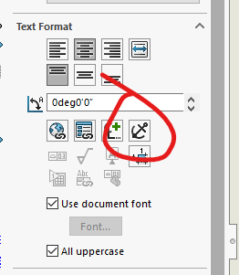
Can you change your font?
Don’t use curve font. Use more straight line font.
Or sketch them out in CAD. Line and arc only.
This is a CNC toolpath problem. The segments are smaller then the tool diameter.
So don’t offset the tool outside or inside the path. Run tool center on the path.
Laser has diameter. All default to offset for accurate part dimension.
It doesn’t matter on marking.
The font has no incidence if it comes from SolidWorks.
We can do it on AutoCAD, which is what we will continue doing. I was just hoping I could find a way to do it in SolidWorks. We could most likely do it by making the text directly in the drawing, but that’s not a route we’re willing to go.
Do you PRINT your drawing as a PDF using the PDF printer or SAVE AS your drawing as a PDF?
These are very different things.
Save as uses vector fonts I believe.
This is my settings:
image.png
We’ve used Save as PDF and it didn’t change anything for them. The issue is the text isn’t actual text, it’s “sketch text”. If it were in the drawing, then it would most likely export as a vector, but that defeats the purpose if we were to have to do it from the drawing.
Have you tried exploding the text and then extruding/cutting it? So that it comes through as actual geometry instead of sketch text? Of course, it isn’t smooth arcs at that point, it is either straight lines or splines. Which may make the issue worse.
We did extrude and cuts without exploding so I doubt it would change something, even if it did, it would defeat the purpose sorta. The way I see it, the text needs to be “selectable” after being printed, so that it can be vectorized. To be selectable, it has to be created in the drawing as far as I can tell.
I missed that earlier. There seems to be a hard coded tesselation for sketch text. I tried wide swings in scaling, and a few different fonts, but the results were the same.
Not so Frederick, been doing all sorts of engraving via CNC since 92 using surfcam from dxf drawing file from Industrial Designers and Artsy customers, and I moonlight making custom parts for bike builders… HARLEY not pedal, cutting designs into derby and points covers.
If SW can use the geometry to cut or extrude CAM can cut it. SW just stalls when it has a shitload of sketch geom.
working on some custom tank badges right now, had to scan the tank to get the shape fist now designing the badge.
leny
A little late to the party, but I would agree with your assesment that the text would have to be created in the drawing in order to export as text. Once you “bury” it in a sketch or worse in a cut/boss feature, it’s just geometry with lines/arcs/splines as far as PDFing is concerned.
Is there some reason you’re not wanting to add the text in the drawing? It would seem to me that’s just as good as adding it in AutoCAD or something.
I feel if the text were to be in a drawing it would most likely be harder to position, we will give it a go at recreating it and try to position it using the existing sketches in the part. My boss wasn’t really eager to go that way for no particular reason so we’ll just give it a go without telling him, see if it works and if it does, we’ll see how ‘intuitive’ it is to work that way and if it’s workable, we’ll present it to the boss as an alternative to paying fees for VMWare and other softwares.
So if you create a note, you can position it by snapping any of these 9 little dots to entities on a drawing view. Unfortunately, I’ve not found a way to make them actually constrained to those entities so that they move automatically if the geometry changes. You can, however, click the “Anchor” button and they’ll be locked in position relative to the drawing view if the view moves, and can’t be accidentally relocated.
image.png
You may be SOL for the text on an arc though. I don’t know of a way to make a note do that.
The only way I can think of to put text on a curve in a drawing would be a painstaking process… Letter by letter. Each letter of the text would have to be a separate note, rotated to the specific angle needed. The angle and spacing along the arc would also not be equal due to different width characters.
If I had to do it, I would probably create the text on the curve in a sketch, then draw construction lines on that sketch that hit the center of each letter. Then I could measure the angle of each construction line to know how much to rotate each letter by, and I’d have an intersection point to snap each note to. I wouldn’t want to do more than one or two…
And while your are doing that I’m going to… ![]()
Great minds think alike, this is sort of how we work-around the model limits in order to do circular patterns.