I am trying to export a circular part to .stl for 3D printing. What I’ve found is that .stl geometry is formed by polygons, which gives a surface that is polygon shaped, not circular (closer to being a stop sign than a circle). Since the 3D printer will attempt to produce whatever geometry it is given, this results in a noncircular part.
Is there any way to produce a circular part in .stl (or .obj)? I already understand that I can crank up the resolution in .stl to improve the stop sign effect, but this doesn’t eliminate it.
I’ve had this problem before, I got a cylinder that was supposed to seal against a plunger/o-ring and there were about 20 faces that made up the interior surface of the cylinder. As you can imagine, the o-ring didn’t seal at all.
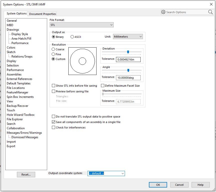
System Options → Export
Adjusting these options to a finer (smaller) value will yield more facets making your part more circular. Be careful though, increasing this seems to exponentially increase the exported file size.
Alex and Frederick, thanks for your advice. I’ve tried everything, but have come to the conclusion that there is no other way. Lots of triangles (which take a long time to generate) and live with the imperfection. Strange that the printer can’t use real geometry like .step.
Yeah, I’m curious too if you can share. I have access to a few different processing programs for our Stratasys printers so they may behave a bit differently as well for processing.
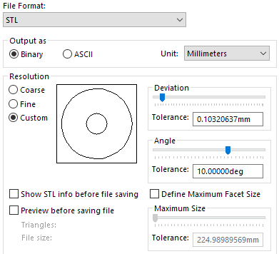
Here’s a defeatured model you can look at. I greatly reduced the deviation and angle tolerances to decrease the size of the flats, but they’re still there.
You settings should be like shown in the image. This is more than enough for even the higher end process… SLA, Polyet…etc.
Alternatively there is also (.3MF) which is “trying” to become the new standard universal file format for Additive Manufacturing. There are a ton of benefits that it has over the older file formats the challenge is that the slicing software for the printer has to be able to import it.
Gentlemen, I appreciate your efforts. It looks like it isn’t possible to eliminate the facets, only make them smaller. I guess I can live with this; it just seems like it ought to be possible to make a circle. Thanks again.
Yes, I tried .3mf, but it has the same problem and took a very long time to export. It would add an additional step of processing through other software to convert to a format that the 3D printing software can read (.stl or .obj only).
There are free / demo versions of several other cad software. (NX, SE, F360 that I know of.) If this is a solidworks limitation, you could export the parasolid to one of the other platforms and then generate the stl/3mf from there.
(ETA: The facets aren’t a solidworks problem, but it might be possible to make them smaller in other software.)
I ran it through the stratasys slicer we have and it seems to have a built in smoothing for faceted curves. It ended up making the faces into arcs. I can’t really output it to any useful formats for you though…
What machine are you printing on that if you change the settings to like I showed, are still showing up in the physical model? That there are facets on the model is correct, that is what a mesh is. Even if it could take a (.step) file, which some slicers can do, it will still convert it to a mesh before creating the G-Code.
If you have images of the model printed after changing to the settings shown I’d like to see the results if it can be shared.
That is how 3D printing works. It will be polygons no matter what you do. It doesn’t matter what CAD software you use if it is a polygonised file format like STL or 3MF. It is a legacy of the beginning of the technology in the 80s.
If you need a real circle not a polygon with 1000 faces you have to use a CNC.
Not to 100% disagree with you on where you’re going with this, but it is possible to get a very smooth surface with with various AM processes. Polyjet, SLA…etc. and very little to none shows in terms of facets. Some of what you can get for jewelry and lost wax casting is just mind blowing.
What he hasn’t really outlined is where he’s taking the model to when getting the model 3D printed.
[quote=“Arthur NY” post_id=23417 time=1664837663 user_id=243]
Not to 100% disagree with you on where you’re going with this, but it is possible to get a very smooth surface with with various AM processes. Polyjet, SLA…etc. and very little to none shows in terms of facets. Some of what you can get for jewelry and lost wax casting is just mind blowing.
What he hasn’t really outlined is where he’s taking the model to when getting the model 3D printed.
[/quote]
Well, not sure about what smoothing OBjet Studio has but yeah, there are ways to further smooth other tools like this freebie..
zxys001 Yes, software like this is great in ways that it allows for smoothing to happen either globally or locally by using a brush. Which isn’t something you can do upon export from most softwares. Some additional ones to take a look at are Blender, zBrush, 3D Coat, and Modo also have similar tools because AD has stopped all development of Meshmixer and knowing them they will pull even being able to download it once it’s folded into Fusion 360.
I don’t disagree that you can get smooth surfaces from polygon models. With enough polygons the difference from a perfect circle will be smaller than the capability of the machine to make it. However, if the OP is looking for an actual circle (or cylinder) in the model it is not how polygon file format like STL or a process that uses those models work. I don’t want them to keep trying to make grape juice out of apples. They have to accept the limitations of the process they chose.
You have to use surface or solid model like a STEP file and CAM software with a CNC machine if you want to see circles in the models or G-code. Even then if you want circles you have to program the tools paths and post the G-CODE that way.