Hello, I admit it’s rude to write a request without first formally introducing yourself, but I really have an urgent matter at hand. I hope to be able to put it right in the future.
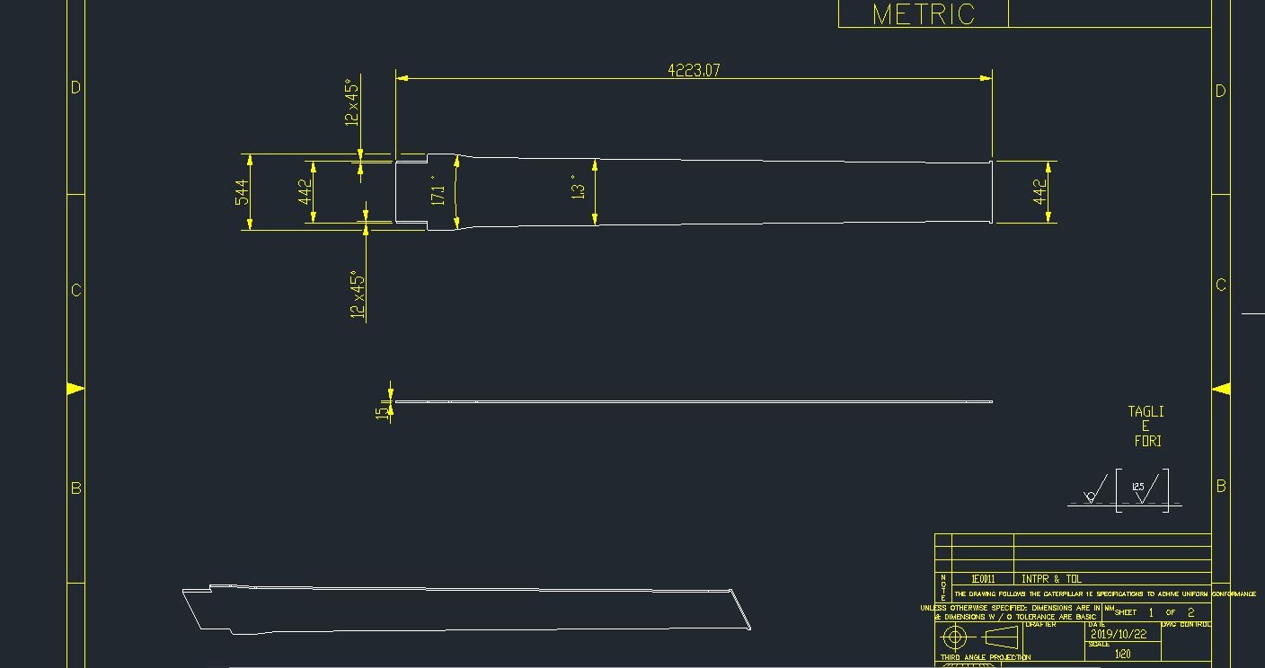
I have been given dozens of technical drawings of steel flat plates with bevels in the thickness, and they’re all in the american orthogonal projection method. Since we are an Italian company we usually deal with drawings in the European layout. I am in charge of entering these drawings onto the nesting machine interface with bevels already set in place, so obviously I need to understand them first, and no-one, even above my position, can explain how to logically and directly interpret them.
The 3D view on the side seems to clarify any doubt I have but I’d really like to understand this system so I can easily handle other drawings of the type in the future without too much struggle.
If they were drawings in the european design, I would assume than the plates in pic 1 and 3 have an upward bevel (for the continued line in the projected place in the upper view), but the downward bevel in the thickness view seems to prove this wrong.
Some colleague hints that the upper view is in fact the lower view, but besides from being it utterly unusual (first time ever for this load), there’s no indication of it whatsoever.
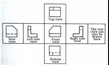
1st and 3rd angle projection should be relatively easy. American standard (ANSI) is 3rd angle. Let’s say you want to make a drawing of your right hand. Look at the back of your hand (but call it the front). To make a left side view, you would turn your hand so the thumb is up toward you (as if you were looking at your hand from the left).
If you are more familiar with the first-angle projection and if you have both the SolidWorks Part and Drawing files for each part you can easily go into the drawing file and tell it to use the first-angle projection rather than the third-angle projection.
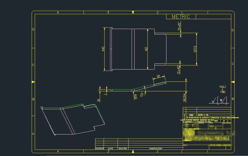
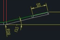
The TB says 3rd angle, but I swear the views look like it was generated as 1st angle. The chamfer on the left should be represented as a hidden line and the bend tangents on the top view line up with the bend radius of the underside on the front view, not the top side.
image.png
I agree that it should be a hidden line. But if you look at the ISO view, you can see that the bend angle is away from us, but the chamfer is toward us.
image.png
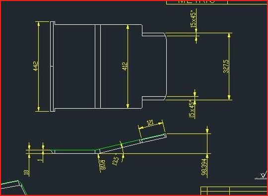
Sometimes hidden lines show up as solid when the resolution is poor. If you zoom in on those drawings, does the line resolve to a hidden line?
What format are the files in? They don’t look like .pdf files but actual AutoCAD .dwg files opened directly? If the latter is the case, then the hidden lines may be set to a different line-type-scale and hence the hidden lines aren’t visually showing as intended (but may be when printed or exported to PDF). Or any number of other things that have this effect.