Sorry, I was replying to the OP and had not seen your reply prior to my response, but thanks for the laugh 

I leave sign off for several hours & come back to this?!
For your information the wall thickness in the older part of my house varies between the ceiling in and the floor. Some places as much as ½"! I never saw a wall built the way they are built. Inner walls are 2X4 studded wall with like ¼" dry wall on both sides covered with a steel mesh & plastered. Most if not all have more plaster near the bottom than the top.
I have to admit that I did close to 100 house surveys and drew them through the years in AutoCAD, Revit, Rhino, Onshape and SolidWorks…
The quickest way to get an accurate floorplan is to measure a few triangles in each room so you know where the walls are farther away from 90deg to “take up the slack”.
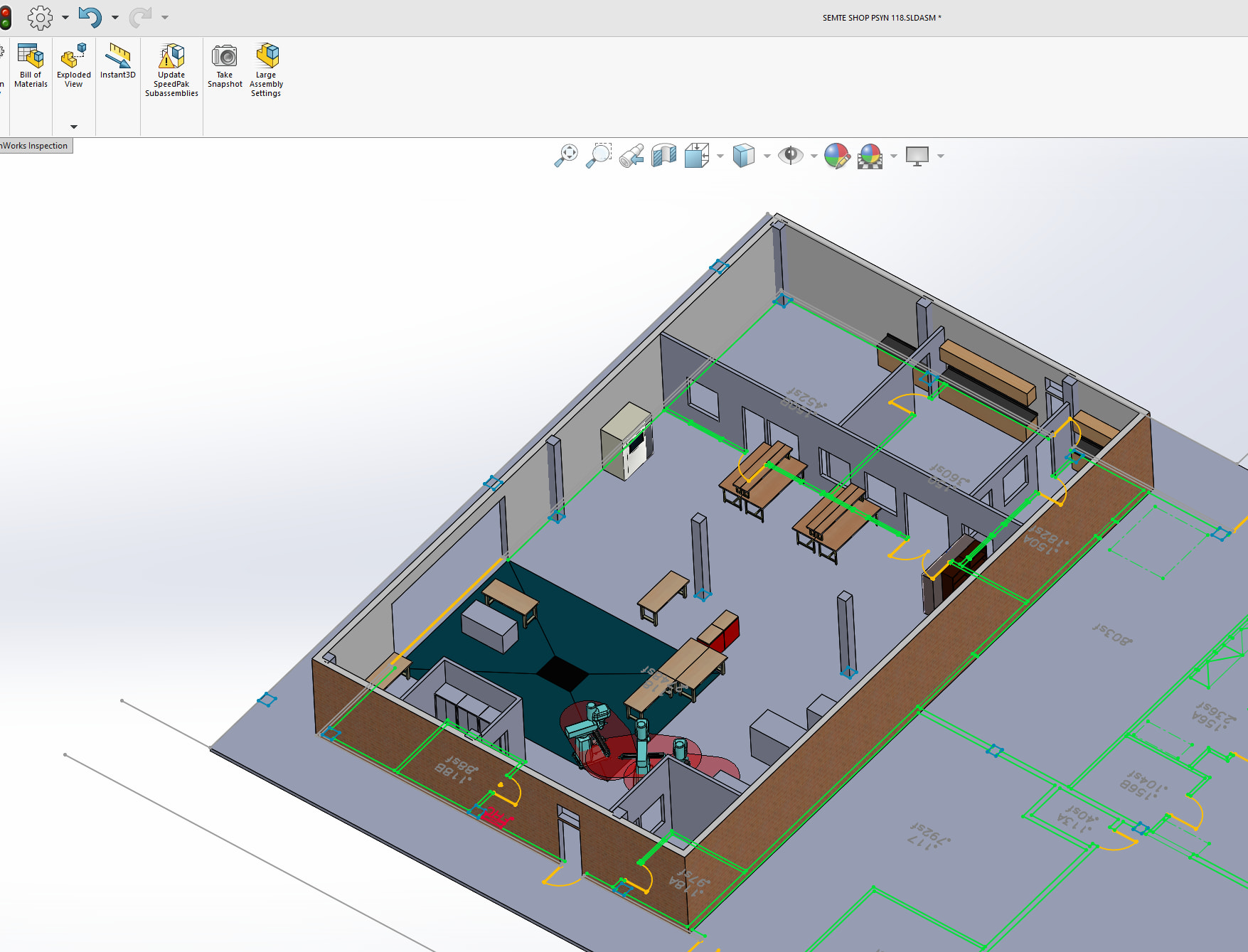
have them send you the 2D DWG, then all you have to do is open the layer with just the walls, then extrude using contour select tool picking the regens, BAM done. did it for our shop here at ASU.
He has a photograph of a paper print of what looks like a standard design offering from a house plan company… My guess is that access to an electronic version would entail somewhere around $1k additional outlay if it’s even possible.
He said he was buying the house, digitals planes can be negotiated 
Just got a server room plan in DWG.
The room is 408.052 in x 439.432 in.
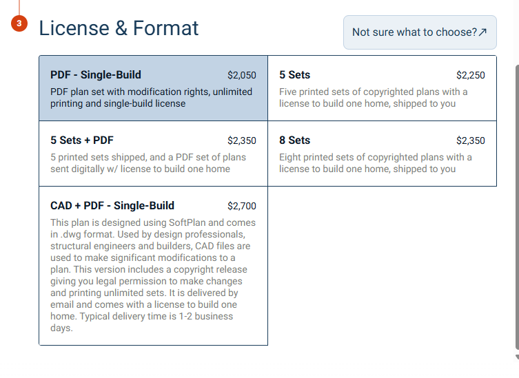
Not necessarily. This house is already built. I doubt this was a custom design, and even the builder may not have access to the electronic version. The seller may not even have relationship with the builder. I’ve only bought house plans once before, but if I recall correctly I got 6 paper copies, all with big red stamps on them stating that reproduction was strictly prohibited. I don’t recall DXF even being an option. Copyright reasons. Commercial house plans and custom design/construction are different animals.
All it takes is a good a great 6 pack of beer and their favorite bottle of hootch…

Again… ONLY IF THE PERSON YOU ARE NEGOTIATING WITH ACTUALLY HAS ACCESS TO THE THING YOU WANT!!!
The current owner may not be the builder.
The builder may have built the home without access to the CAD.
Here’s just one commercial house plan site… Only one of the purchasing options comes with CAD. I don’t see an option to purchase just the DWG, or a way to enter “hooch” as payment.
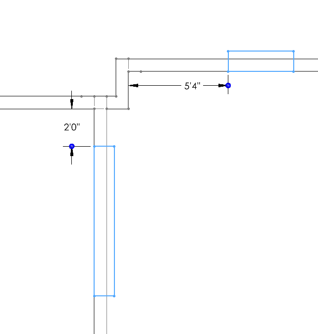
I’d avoid thin extrusions. It’s a pain when there are exceptions, and you want to get more accurate on actual wall thickness. I think it’s worth sketching the extra lines.
Could try room walls as extruded surfaces, resting on one main sketch. Then they can be shifted around, keeping room shape, when you care to detail the wall thickness. It depends what changes you end up making in the future, but the surfaces approach is probably more adaptable than having lots of unified solid walls in one extruded body. This falls into the category of things I wish I had tried when I modeled some rooms.
For sure create some reference geometry Planes, and use them. One horizontal plane per floor. Some boundary planes for the outside. 3D floor and ceiling are the last thing you should add.
For example if there are multiple wall extrusions - use “extrude to surface” and pick your ceiling Plane to cap the height.
On your main plan sketch - for spacing the rooms, wall thickness variation, could use equal construction lines - or create a few global variables so you can tweak a bunch of like thickness dims in one go (one wall maybe a thick4, another could be a thick6.25, etc).
Another thing that can help… Sketch the rooms without doorways. Greatly simplifies the dimensions and clutter on your main sketch.
Then put another sketch on top of it with doorways. This is the sketch you will actually extrude up (perhaps surface extrude the walls inside each room). If you extrude rooms as separate features you can more easily label them, not the quickest, but it’s nice to have when done.
Or you can cut the doorways out from the walls. The cutting rectangles in the image are sketch-blocks, since I had multiple doorway sizes.
Don’t you just love it when someone does that? A few years ago a drawing crossed my desk with the embedment of an anchor bolt in concrete shown as something like 6-3/16" (and no, there was absolutely no reason for that level of precision).
Looks like they randomize the number for security reason 
Or they don’t know how to draw/move line in AutoCAD. All dimensions looks good in fraction, decimal are all over the place.
Then they don’t build it to the drawing 
I understand material are not to size. Like 4x2 are not 4x2. Still.
They are probably outsourcing drafting to other countries for the “cheap” rate. Drafters in the US is becoming more and more of a rarity.
LOL!
Thanks for the levity.
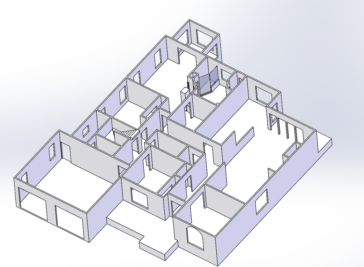
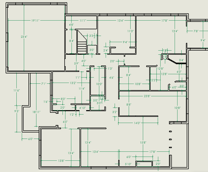
I wound up doing it twice. The second time, I echoed what was on the plan for the rooms, and then space everything out by 4" (which is the dimension on the plan). The plans are bit different than the actual house, so I will definitely need to check dimension.
So basically all the wall are extruded as one body. Then I cut the doors, then the windows.
This is the whole shebang:
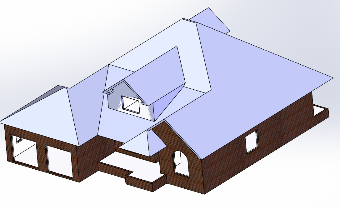
I haven’t put doors and windows in yet, there will be time for that later.
This is the first floor:
First floor drawing
Second floor drawing
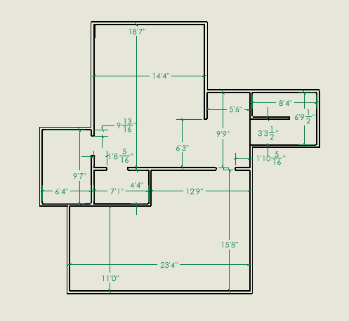
That’s it!
Cheers
nice!