Hi. Every once in a while I get a report of the Display Style not having affect in an assembly. Referring to the bar at top of graphic view.
image.png
Most of the time this will change the entire assembly’s Display, however sometimes it has no affect. It seems to be specific to a file, the user can show the problem on their computer, then if I open the same file I see the same issue on my computer.
The buttons in the Feature Tree of the assembly will still work to set the display style of individual components.
image.png
Is there some document setting that we are switching unwittingly that causes this?
You can change the display of a particular component. You can do this by highlighting the component and changing its display from the right mouse button. In the image below you can see that most of my parts are using the default display state (with the check on the box). The one at the top is using hidden line. If you have a user that is changing a part to be able to “see through it”, that may be what is leading to this.
There is a hierarchy for applying (or seeing, removing, etc) colors, textures, and other visual characteristics. By “hierarchy”, I mean the higher your selection is on this list, the more likely the appearance will show (unless there is another appearance applied to something even higher on the list). Here it is, from highest priority to lowest:
-Assembly (if you assign an appearance to the assembly, it overrides all other appearance options)
-Component (a component is a part or subassembly selected in an upper level assembly)
-Face (doesn’t matter if the face is selected in the part or assembly)
-Body
-Feature
-Part (where the appearance is assigned in the part window, or specifically applied to the part level in the assembly)
Ok, so I tried to make sure I was using the correct jargon so I didn’t get drawn into five directions at once. “Display Style” is the tool that appears to not be working. The answers mentioned “Display States” and “Appearance” I thought those were something else? From the answers it sounds like they are all balled in together some how? Are they all the same thing just given different names in different areas or are they different things but all interdependent? So confusing, why must is be so difficult to change from shaded to wireframe?
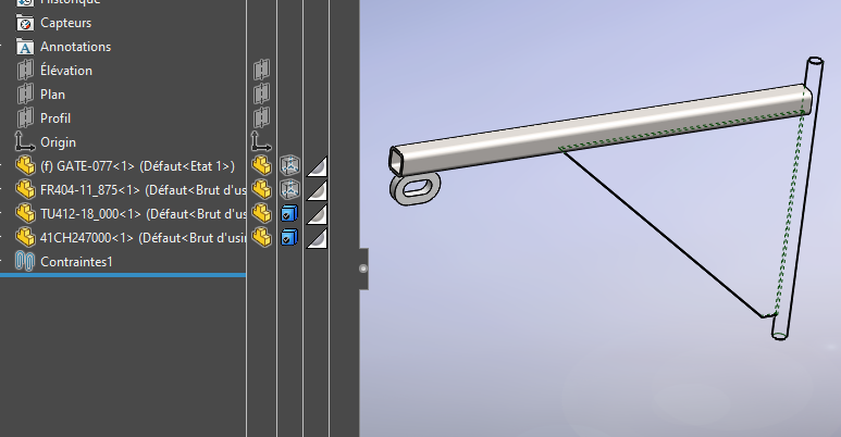
Hi Scott, Before I can properly ask for help I must learn the lingo. I do not know what to call this thing in the assembly environment that is supposed to switch the view from shaded to wireframe, wireframe w/hidden, etc.
image.png
Hey, you’re using the correct term I believe, no worries buddy.
So you’re getting a mix of display styles is what I’m understanding, and even though you open the side-bar, it’s still still showing correctly, and not like this
Thank you Alex. Not exactly. I’m trying to figure out how to take a video of the Solidworks window. the View->screen capture option only records the graphics area so you cannot see mouse/tools interactions. I think I’m save posting a video of this assembly and it will help reduce the guessing game.
Attached gif, thanks for the recomendataion, I was able to just download, run and use; crazy!
Anyway, the dropdown at top of graphics area doesn’t do anything in the assembly, in others it will change display for everything in the graphics area. The Display style (or “view type” maybe) in the feature manager will change one component at a time, as expected.
That doesn’t have any effect because it’s been overridden for all components.
image.png
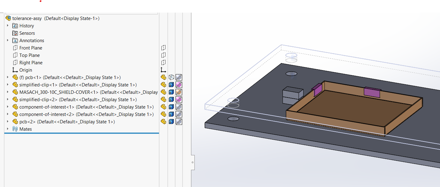
See the screenshot below of the tree in an Assembly I’m working on. Notice all the little check marks on the little blue boxes? That means they’re set to use the Default Display, which is whatever selection is made from the drop-down in the heads up display.
image.png
If you will right-click on the icons in that column for this Assembly and make that selection from the drop-down I believe it will behave as you want.
Good eye Glenn, I had forgotten he said the issue happened on multiple workstations, so it definetly didn’t have anything to do with registry or whatever I said. The checkmark is something I had never noticed because I rarely ever toggle these.
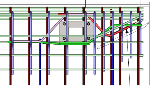
I don’t do it often, but one of the best uses for it is when I need to show complex rebar in an Assembly. I’ll set up a display state with the concrete set to Wire Frame, then reference this display state in my drawing view, with the drawing view set to shaded. Previously I’d set the concrete to transparent, but then it showed gray. By setting it to wire frame only the outlines of the concrete are shown, which improves the clarity.
Exactly as you say Glenn. Thank you! I feel a little dumb though as I was on the solution in the first gif I posted. Watching it must have been like watching a toddler look for Easter eggs. <()>
DisplayStyle_solved.gif
Also thanks Scott for mentioning the screentogif tool. I gained several handy “nuggets” from this thread.